What is modular synthesis?
The routing and manipulation of signals to create sound and music. Modular synthesis
VCV-specific
https://vcvrack.com/manual/GettingStarted All signals in VCV rack are virtual voltages, but they can be classified roughly into a few categories:
- Audio signals are audible if played through your speakers. They contain audio-rate frequencies typically between 20 Hz and 20 000 Hz.
- CV (control voltage) signals can modulate parameters of other modules. For example, and LFO (low frequency oscillator) can oscillate the pitch of a VCO (voltage-controlled oscillator) or the volume level of a VCA (voltage-controlled amplifier).
- 1V/oct (1 volt per octave) signals are CV signals that represent a pitch or a note. In this standard, and increase of 1V increases the pitch by 1 octave. Since there are 12 semitones in an octave, an increase of 1/12 V increases the pitch by one semitone.
- Gate signals carry an on/off signal. 0V represents off, and a positive voltage (typically 10V) represents on. For example a gate signal can turn on when a key is pressed, and off when a key is released.
- Trigger signals are short gates (usually around 1 millisecond) that cause an event to occur, such as a percussion hit.
- Clock signals are triggers played at a steady tempo, in order to set the musical timing of your patch.
Modules
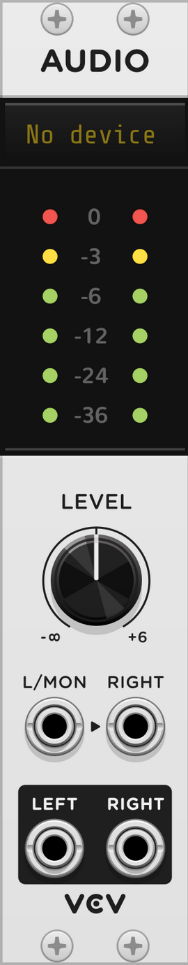
Audio
https://vcvrack.com/manual/Core#audio The most important module! Without it, you won’t hear a thing. The VCV Audio module is the portal between the physical and the virtual world. It sends audio from the VCV rack to your speakers. It can also receive audio from microphones and your audio device’s inputs. Don’t forget to set the right output device, e.g. headphones or the built-in microphone of the computer.
MIDI > CV
https://vcvrack.com/manual/Core#MIDI-CV Converts MIDI notes from an external MIDI device to CV and gate signals. That CV information then goes into e.g. a VCO. MIDI input can be from laptop keyboard, electric piano keyboard, game controller, etc.
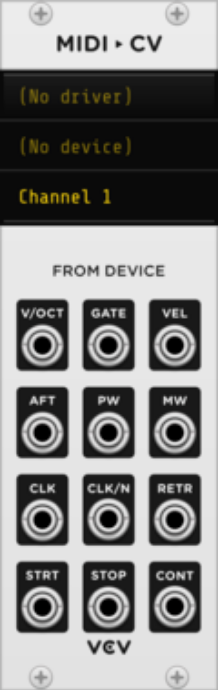
V/OCT generates 1V/oct pitch signal of the last held MIDI note. Takes MIDI pitch information and converts it to pitch information (voltages) that Eurorack modules can understand. E.g. C1 = 0 volts, C2 (one octave up) = 1 volts, C3 = 2 volts. Notes in between have fractions of volts, e.g. 1.25 volts. Connect V/OCT output to V/OCT input on a VCO ⇒ VCO receives pitch information from the MIDI input.
Gate output = on/off switch. Either 0V (key not pressed) or 10V (key pressed) signal. Can be turned into something a bit more nuanced with an envelope generator. Gate signals can be shaped by an envelope generator. By connecting an ADSR to the gate output, we’re saying: “Turn the ADSR on when a note is pressed, and turn it off when it isn’t.”
Righ-click the module to enable polyphony, and select the number of polyphonic channels. Makes it possible to overlay several notes at once. Polyphony mode selects the order in which those newly pressed notes appear in the selection .
VCO - Oscillator
https://vcvrack.com/Free#VCO = voltage controlled oscillator **Generates raw tones at a particular frequency (pitch). Creates constant oscillations. Creates the sound/tones. **
Can make sine, triangle, saw and square wave forms.
- Sine wave = sounds clean and round.
- Triangle wave = sounds clean but less warm than sine.
- Square wave = piercing sound
- Saw wave = sharp sound
Can change pitch, usually with the big FREQ knob or with the port that is labelled V/OCT (= increase voltage by 1 to increase pitch by 1 octave).
Most VCOs are free running, i.e. always on. (If you plug the output of one of the waves into the audio module, it’s going to make a tone).
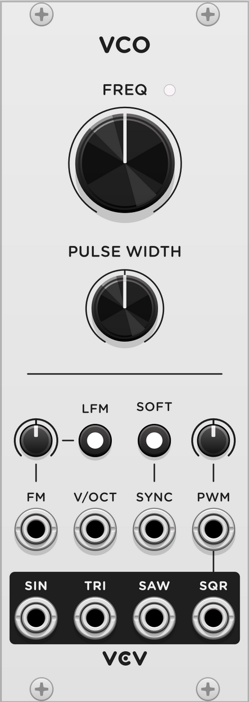
Frequency knob controls the pitch. Default = 261.63 Hz, i.e. C (C4, middle C).
Pulse width can be controlled by the Pulse Width knob and modulated by the PWM (pulse width modulation) CV input and attenuverter. By default it’s 50% of the total wavefrom. Higher and lower pulse widths give reduced harmonics for a thinner sound.
To control the pitch with another module, path a CV signal into the V/OCT input or the FM input. V/OCT multiplies the frequency value using the 1V/octave standard, i.e. each volt of CV increases the pitch by 1 octave, meaning each 1/12 V increment increases the pitch by 1 semitone.
FM input applies an additional pitch adjustment with the attenuverter knob. At 100%, the FM input functions like the V/OCT input. Press the LFM button to enable linear frequency mode; the oscillator’s frequency is adjusted proportionally to the FM voltage, rather than exponentially.
VCOs are usually always on. Often, their amplitude is controlled with an envelope generator (ADSR EG) and a VCA.
LFO
https://vcvrack.com/Free#LFO =low frequency oscillator Creates continuous oscillations below human hearing. Like invisible hands that can turn knobs for you.
Very similar to VCO. LFO is more suitable for generating CV for modulation (while VCO is more suitable for generating audible waveforms).
LFO is handy when you want to create continuous motion whether or not pressing keys on a keyboard.
Can be connected well with envelope generators.
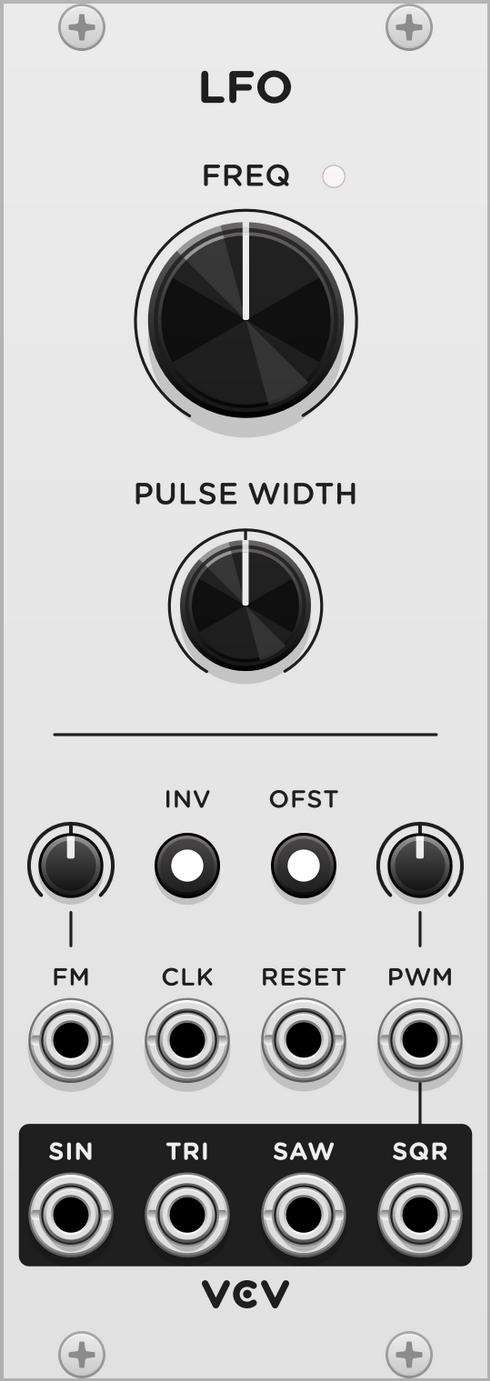 Range of the FREQ know is much lower than for VCO, ranging from one osciallation every 4 min to about 1000 Hz.
Square wave on an LFO can also be used as a gate signal input for e.g. an envelope generator.
VCA - Amplifier (like a volume knob or fader)
https://vcvrack.com/Free#VCA-1 = voltage controlled amplifier Think of it as a volume switch. Can be turned up or down, either by hand or by voltage.
How much of the input signal is going through to the output.
The VCA applies gain/attenuation to an audio signal or CV signal according to another CV signal. E.g. you can control the volume level of a synth voice with an envelope generator or sequencer.
Hast two inputs: one that controls the level (can be dynamic) = CV in, and one that just feeds through and takes the level that is (manually) set = channel input. E.g. the output of an ADSR goes into the upper input so that the ADSR modulates the amplifier.
 E.g. Output from an ADSR envelope is going into CV input. The volume on the VCA is now controlled by the ADSR and reacts according to where in the envelope we are at any point in time.
ADSR - Envelope generator
https://vcvrack.com/Free#ADSR Shapes the timbre over time. Allows you to shape the timing of the synth, e.g. to fade the sound in gradually. Envelopes put out SHAPES. They can shape volume, or pitch (frequency) or filter cutoff, or wherever else you plug the cable into. Takes the crude on/off information from the MIDI gate input, and creates a more nuanced sound: Connect the gate output from MIDI input to the gate input on the ADSR.
When a gate signal enters the GATE input on the module it will initiate the ADSR sequence. This can be done e.g. with a clock.
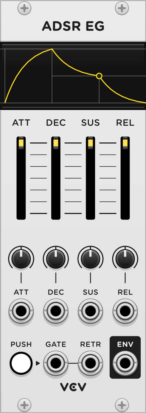
The envelope generator converts a gate (on/off state) into a CV signal with a musically useful shape. Often used to control VCAs. Also, often there’s one dedicated envelope for the volume, and one for the cutoff on a filter (e.g. VCF ⇒ ENV output on envelope into CUT input on VCF).
The ADSR envelope generator was developed in the 1960s as an attempt to emulate the behaviour of physical instruments, such as the piano.
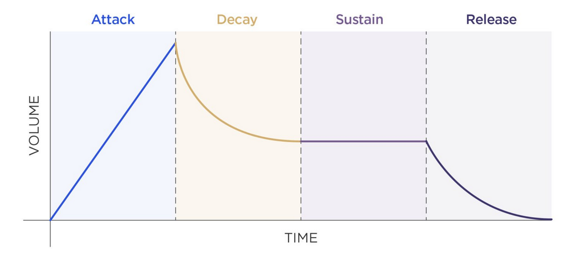 (From https://mastering.com/modular-synthesis/)
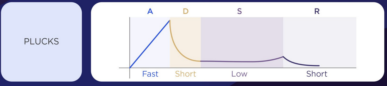
Attack: How long it takes for the synth to reach full volume. Rising time while the gate is HIGH. Decay: How long it takes for the synth to fade to its secondary volume. Falling time while the gate is HIGH. Sustain: How loud the synth is after reaching secondary volume. Target CV level while decaying. Release: How long it takes for the synth to completely fade out. Falling time when gate is LOW.
Examples of sounds from ADSR
(From https://mastering.com/modular-synthesis/)
Plucked sound: Short attack, medium decay, no sustain and release.
Others:
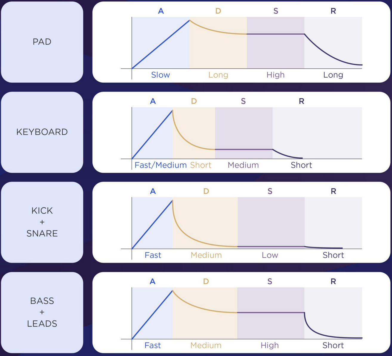
Short attacks are plucky, long attacks are swells. Long releases take a long time for the note to tail off.
VCF - Filter
https://vcvrack.com/Free#VCF = voltage controlled filter Removes a range of frequencies from an audio signal, with its cutoff frequency controlled by an external voltage.
Brighten up or dull down the timbre of a tone. Takes away (subtracts) energy from the input signal. Filters are used in many types of synthesiser patches to control the intensity or harmonic richness of audio signals.
Works best with wave forms other than sine wave, e.g. a saw wave.
LPF = low pass filter. Let’s the lowest pass through as the cutoff goes down. HPF = high pass filter. Cutoff dial to the right.
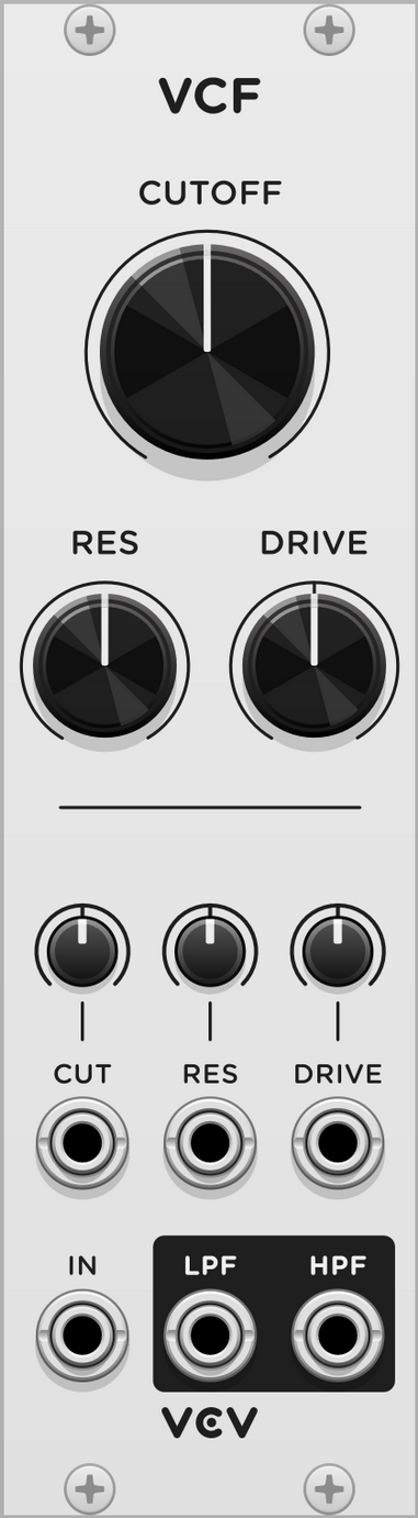
CUTOFF knob sets the characteristic frequency of the filter, the point where it begins to attenuate frequencies. Set to where the cutoff frequency should start from (8-8000 Hz). If set to 100%, the cutoff modulation input controls the frequency with the 1V/octave standard.
RES knob controls the filter resonance, which emphasises the signal near the cutoff frequency.
DRIVE knob adds gain to input signal. Creates a dirtier, grungier filter sound.
CUT cutoff input slot: Lets us control the filter cutoff using other voltages. CUT attenuverter: Set to amount that the big CUTOFF dial should react to. If it’s set to 100%, the big cutoff dial will, with every signal, turn all the way to maximum. If it starts at 8 Hz, it would go all the way up to 8000 Hz. If set to 50%, the big cutoff dial would go a half circle. Patch for example the ENV output of an envelope generator into the CUT input on the VCF. Turn attenuverter high (100%) and the cutoff knob low to get the most effect.
SCOPE
oscilloscope https://vcvrack.com/Free#Scope Makes the waves and signals visible.
An oscilloscope visualises voltage signals over time. Good for understanding CV and audio signals.
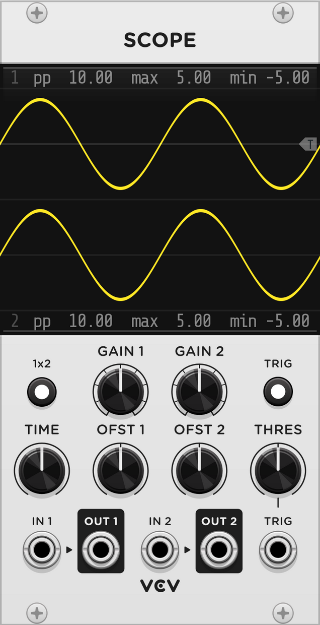
Patch any cable into IN1 or IN2 to see its voltage over time. Outputs OUT1 and OUT2 are provided to pass the signal through to other modules.
TIME knob zooms the screen horizontally (5 ms - 50 sec). GAIN knobs zoom the screen vertically. OFST knobs pan the screen vertically.
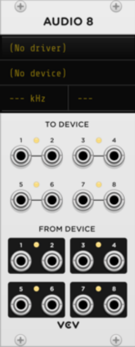
AUDIO 8
Audio output
Notes
- V/OCT = volt per octave. One volt up is double the frequency, i.e. one octave up.
Sequencer (Step sequencer)
A sequencer can be used to program patterns of melodies, control voltage, or triggers for playback. VCV SEQ 3 can sequence up to 8 steps, each with 3 channels of CV and 1 channel of triggers.
SEQ3 = three rows of eight knobs.
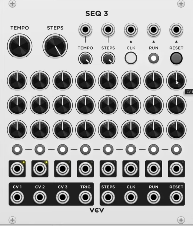
Many step sequencers have two major outputs:
- One sends a TRIGGER: Useful for initiating ADSRs.
- One sends a VOLTAGE: Useful for changing pitches, so it can be connected to the V/OCT input on a VCO.
Quantizer
Quantizer rounds a 1V/octave pitch signal to the nearest enabled note. By default all notes in the chromatic scale are enabled, so Quantizer simply rounds the pitch signal to the nearest 1/12 V.
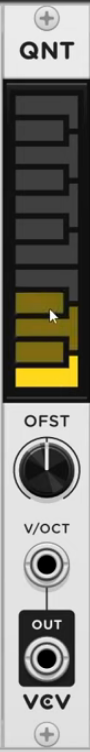
The OFFSET knob adds voltage/semitones to the pitch signal before being quantized.
Exclude certain notes by clicking the piano keys. E.g. select only keys that fit a certain scale. It will then restrict the input (e.g. an output from a step sequencer) to that scale.
Clock
Give us steady gates or triggers at specific bpms, and are used to keep time and sync modules. E.g. CLKD by IMPROMPT
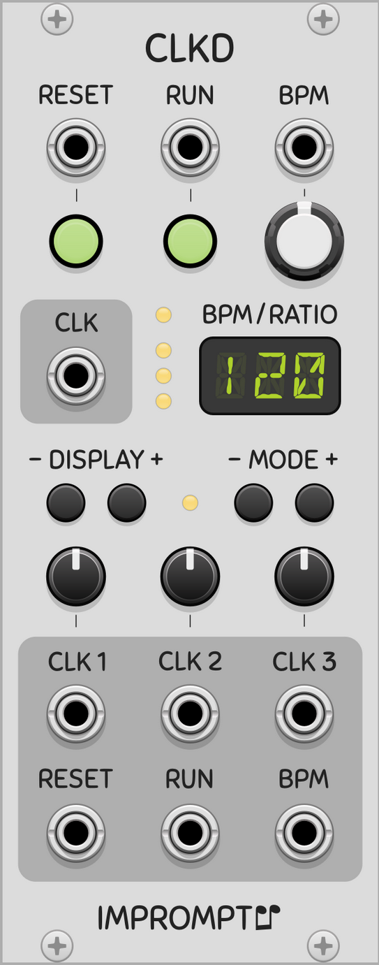
Set the bpm to a desired value, e.g. 120. To trigger it at every 8th note, set it to 4x the clock value. If you want two notes to play in time with each other: Either use the same clock output to initiate it (i.e. two cables coming out of the same clock), or use a different, synced clock. E.g. CLK1 output for one note, CLK2 output for the other note. Those clocks can run at different bpms, but will be synced.
Sample & Hold
Constantly read an input voltage. When they’re triggered, the snag the voltage at that instant and perpetuate it through their output. So every time it triggers, it’s going to snag a new voltage.
Slew Limiter
Even out abrupt changes. We can control how long that change takes and the shape of the change. For example, route a CV signal through it, coming from a Quantizer, going to a VCO.
Bernoulli Gate
Accepts an incoming signal and send it to either A or B output, based on probability. The probability can be altered to make events more common or more rare.
For example, use it to every once in a while make the melody or beat skip a note.
Tutorials
Your Pal Rob
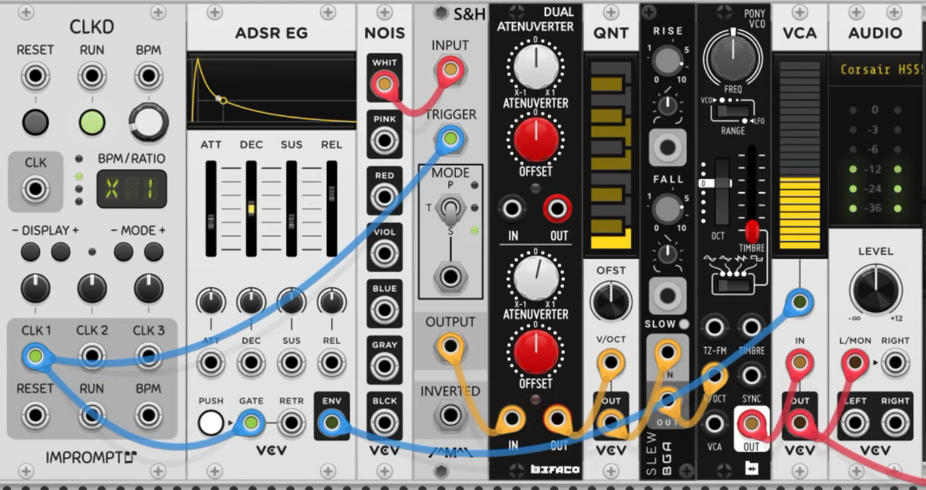
# VCV rack tutorial: Cabling the right way
https://www.youtube.com/watch?v=kT4h5TMHTBs
- Hover over the end of a cable to see the name of the port where the other end of the cable is, as well as the voltage that’s running through it.
- Monophonic cables are thin. Green light for positive voltages, red light for negative voltages.
- Polyphonic cables are thicker. Blue dimming light for voltages.
- Ctrl-click on one port to create multiple cables coming from it.
- Common cable colour coding:
- RED: audio information
- YELLOW: pitch information
- GREEN: modulation
- BLUE: gates & triggers
- Right click on a port to choose the colour of the cable before dragging.
- Biset’s Blank module displays signals across cables.
# VCV rack tutorial || essential modules & what they do
https://www.youtube.com/watch?v=gTxiZ9_Kgyo&t=7s
- Always add an Audio module.
- Put modules that you always use into a Template Patch and save it.
- VCO - Oscillator
- Makes a tone.
- Usually controlled with ADSR envelope generator and a VCA.
- Connect the output of one of the waveforms to the audio input on a VCA.
- VCA - Amplifier (like a volume knob or fader)
- Connect the audio output to the audio module.
- ADSR - Envelope generator
- Produces a variable voltage
- Connected to a VCA it will move the slider up or down, depending on the voltage output: connect the ADSR output to the voltage control port of the VCA.
- Clock
- Sync and keep time, trigger at certain bpms
- Sequencer
- E.g. can be progressed by a clock: every tick of the clock moves the step sequencer to the next step.
- Quantizer
- Snaps values to the closest v/oct that is in tune (i.e. 12 tone equal temperament tuning, like a standard piano).
- Place it between Sequencer and VCO, and it will make the adjustments for us.
Basic setup 1
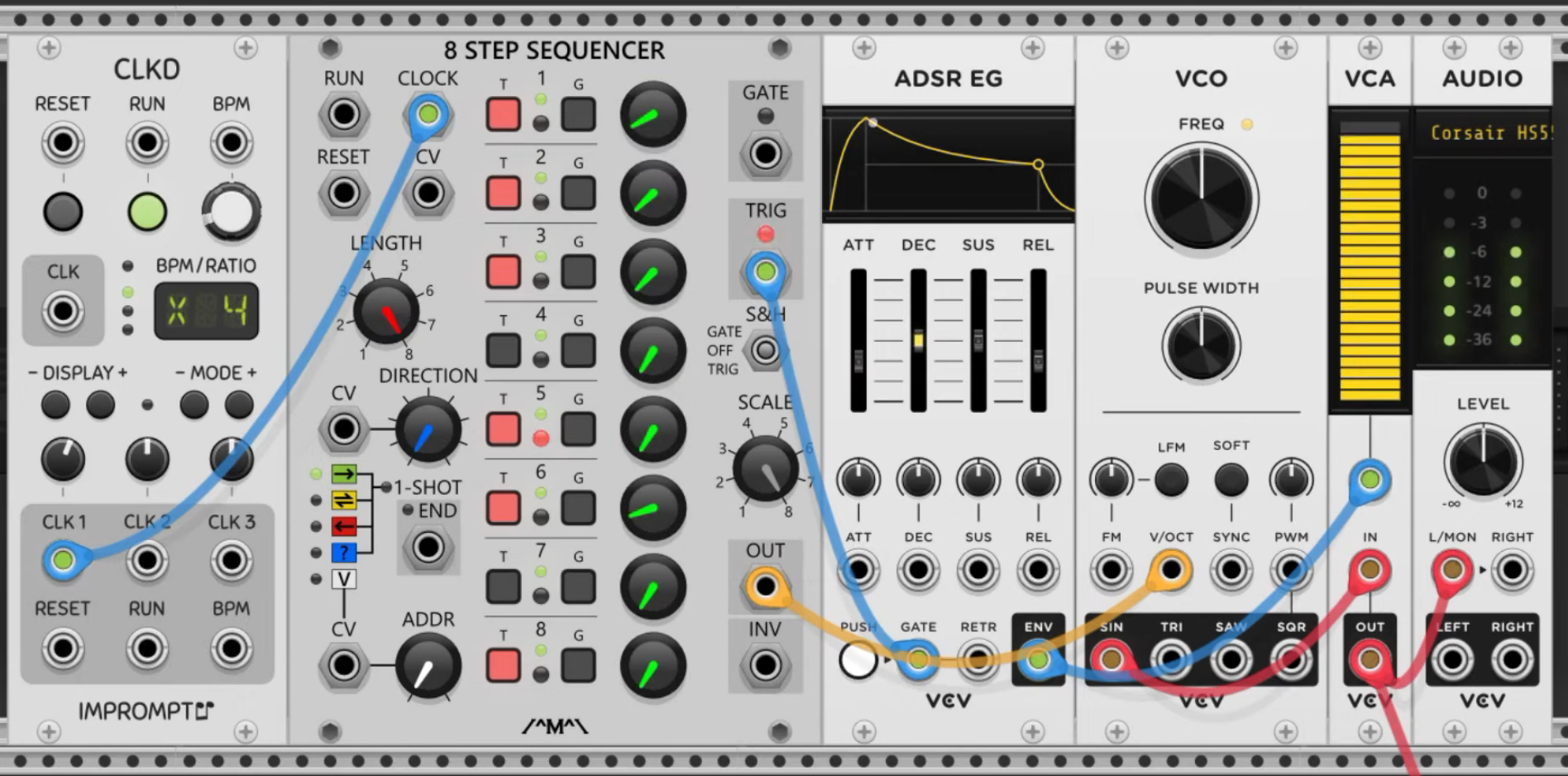
Include a Quantizer between Sequencer and VCO to make it sound more melodic (i.e. “tie” it to a certain scale).
Interesting patches
Hard-set melodies and rhythms can quickly sound very stale. To counteract that, use modulation. Modulation = change parameters with control voltage (CV). How this is implemented makes all the differences in a patch.
E.g. modulate some parameters in the Basic setup 1 patch with an LFO.
- LFO: Move very slowly (slower than 20 Hz). Plug the output from the sine wave into the Attack CV port on an ADSR. Turn the attunverter.
- Attenuverters control the polarity and magnitude of modulation.
- Sample & Hold
- Use a random voltage to modulate the timbre of a VCO.
- Connect a noise source from a noise module to the input of the Sample & Hold module.
- Connect a clock to the trigger or gate input.
- The S&H module snags a random voltage (from noise) at every tick of the clock.
- Connect the output to the timbre CV port of the VCO.
- Generate a random melody.
- Same setup as for random VCO timbre modulation.
- Connect the output of the S&H to a Quantizer v/oct input to quantize the output to a scale, e.g. F minor.
- Now the S&H module randomly selects notes within the F minor scale.
- Connect the output of the Quantizer to the v/oct input on the VCO.
- You can add an Attenuverter (e.g. Befaco’s Dual Atenuverter) to limit the range.
- Slew Limiter
- Put a Slew Limiter just before the VCO and route the CV signal through it
Setup with Sample & Hold and Slew Limiter