https://www.youtube.com/watch?v=ZrcqauNvt0M
Set up user-defined parameters:
- depth, mm, 120
- width, mm, depth x0.75
- ply, mm, 3
- holeSpace, mm, depth/5
- hight, mm, depth x0.5
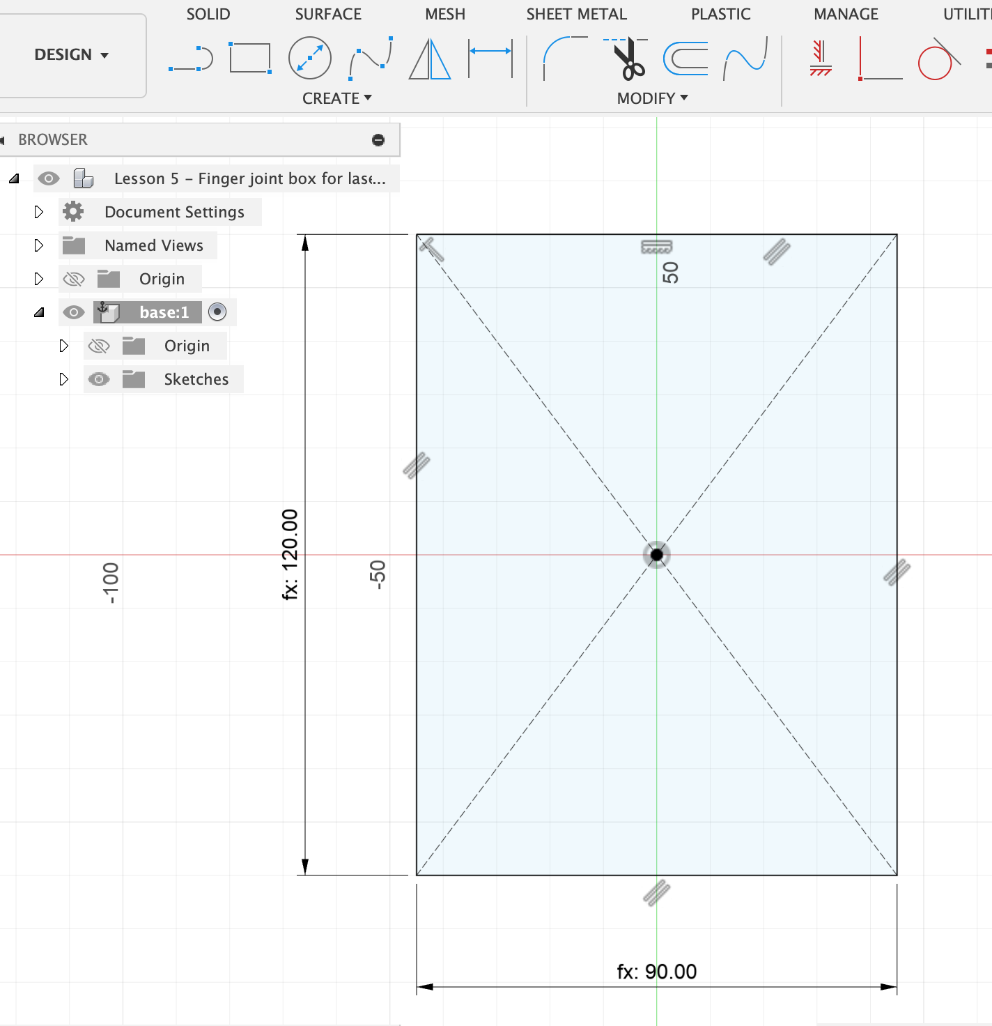
Create > New Component Name it something: base Then, Create > New Sketch. On the bottom plane, draw from the origin a centre point rectangle. Click on the centre point, drag out, then type depth - tab - width to give it the right dimensions.
The sketch of base is now visible in the left-hand menu:
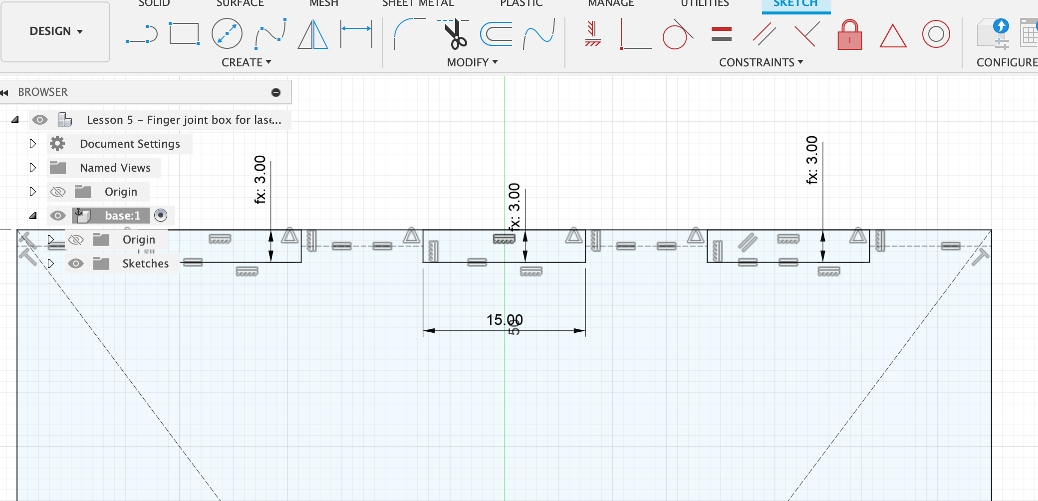
Now we draw some rectangles on the top edge of the rectangle we just drew. Select the 2-point rectangle tool. Draw three rectangles with approx. equal spacing, but it doesn’t matter if it’s accurate and if the rectangles are different sizes. The only important thing is that the upper edge of the rectangles aligns with the upper edge of the base rectangle.
Then select the line tool and draw from the left edge of the base rectangle to the right edge of the first small rectangle. From the left edge of rectangle 1 to the right edge of rectangle 2, etc. Make sure the lines are anchored at the mid-points of the little rectangles. You can see that by hovering and finding the spot where the little triangle appears.
Now shift-select all the lines we just drew. In the right-hand sketch palette menu, click Linetype > Construction. Then select the Equal icon above the Constraints menu, to make the lines all equal length. Press Esc to get out of the Equal selection again.
Then shift-select the lower edges of the three little rectangles, and also click on Equal. Esc.
Then select Sketch Dimension or short-cut press “d”, click the lower edge of small rectangle 1 and the upper edge of the large rectangle. That lets us define the dimension of this. Click somewhere to see the label nicely, then type in “ply” and press Enter. This adjusts the thickness of all three little rectangles to “ply”. Esc.
Select Sketch Dimension and click the lower edge of small rectangle 1, drag down, and type in a round number, e.g. 15. Now all of the three rectangles (the fingers of the joint) are the same size and evenly spaces. You can check that with the Measure tool.
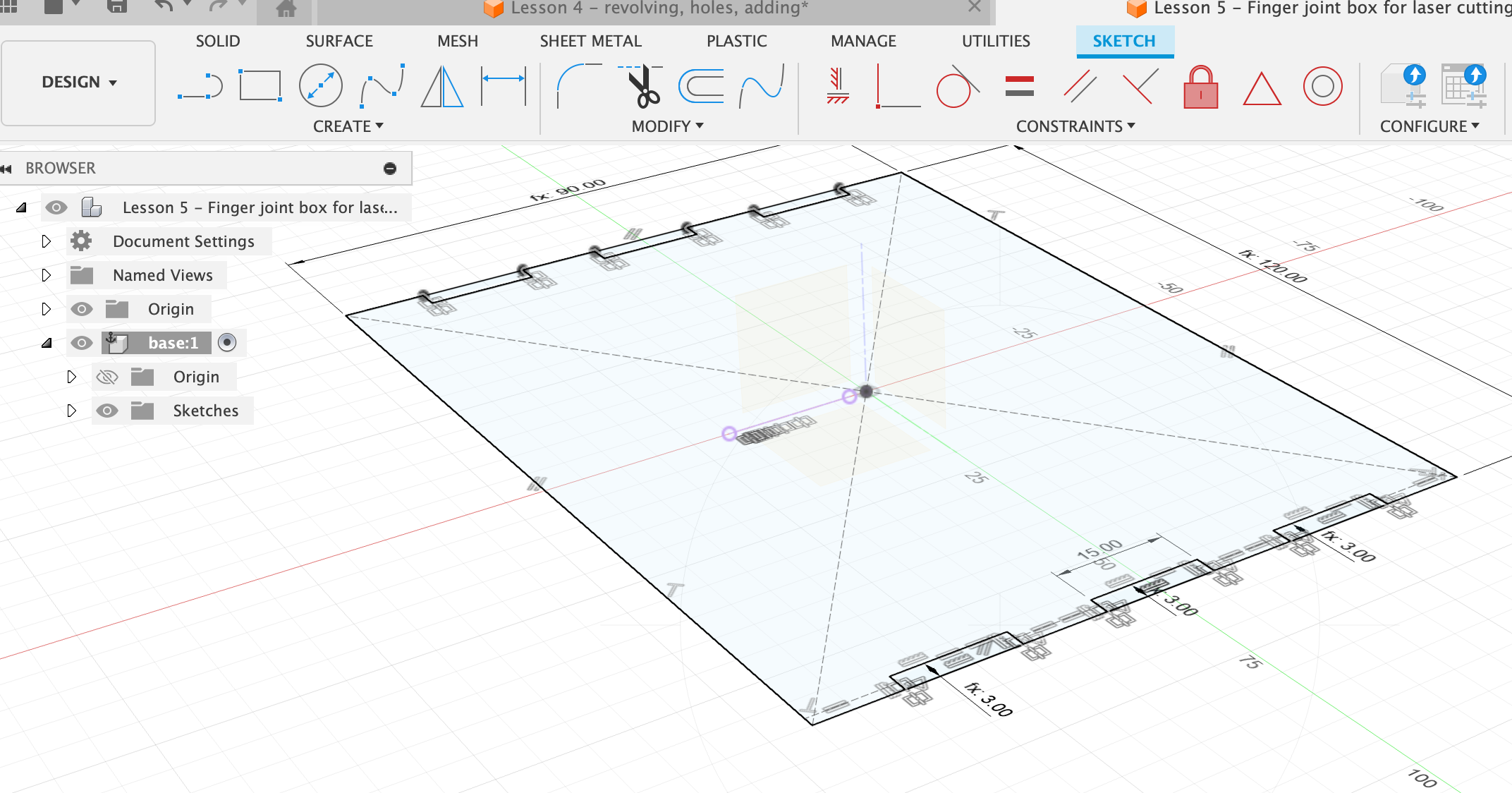
Mirror the fingers across to the other side
Click Mirror then zoom into your sketch and carefully select three sides of each small rectangle: the lower edge, the left and right edges. Make sure to not select anything else by accident. It should be 9 objects selected in the Mirror menu. Then select a mirror plane. Orbit around to see the origin plane. If you don’t see it, it might be turned off. Make sure the eye-icon in the left-hand menu for Origin is active. Now you can select for the Mirror Line the vertical plane so that the three rectangles are mirrored across to the other side.
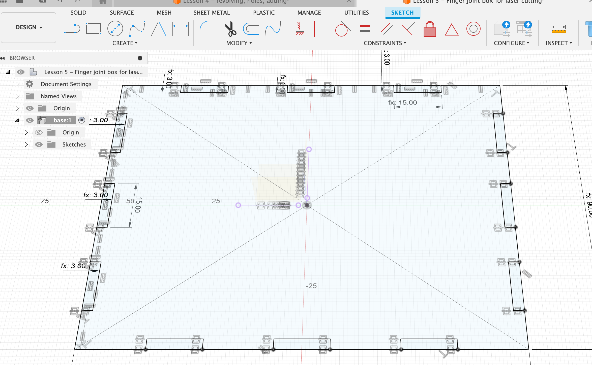
Then do the same on one of the sides of the large rectangle:
- 3 small rectangles
- mid-centred lines between them
- make the lines construction lines (with x)
- make the lines equal length
- make the rectangles equal length
- dimension one of the rectangles to be the same length as an already existing one, by instead of typing in a value click on an already dimensioned small rectangle
- make the thickness of one rectangle “ply”
- mirror: click Mirror command, click the objects that you want to mirror, select the plane.
Extrude in width “ply”. Now we have our base plate:
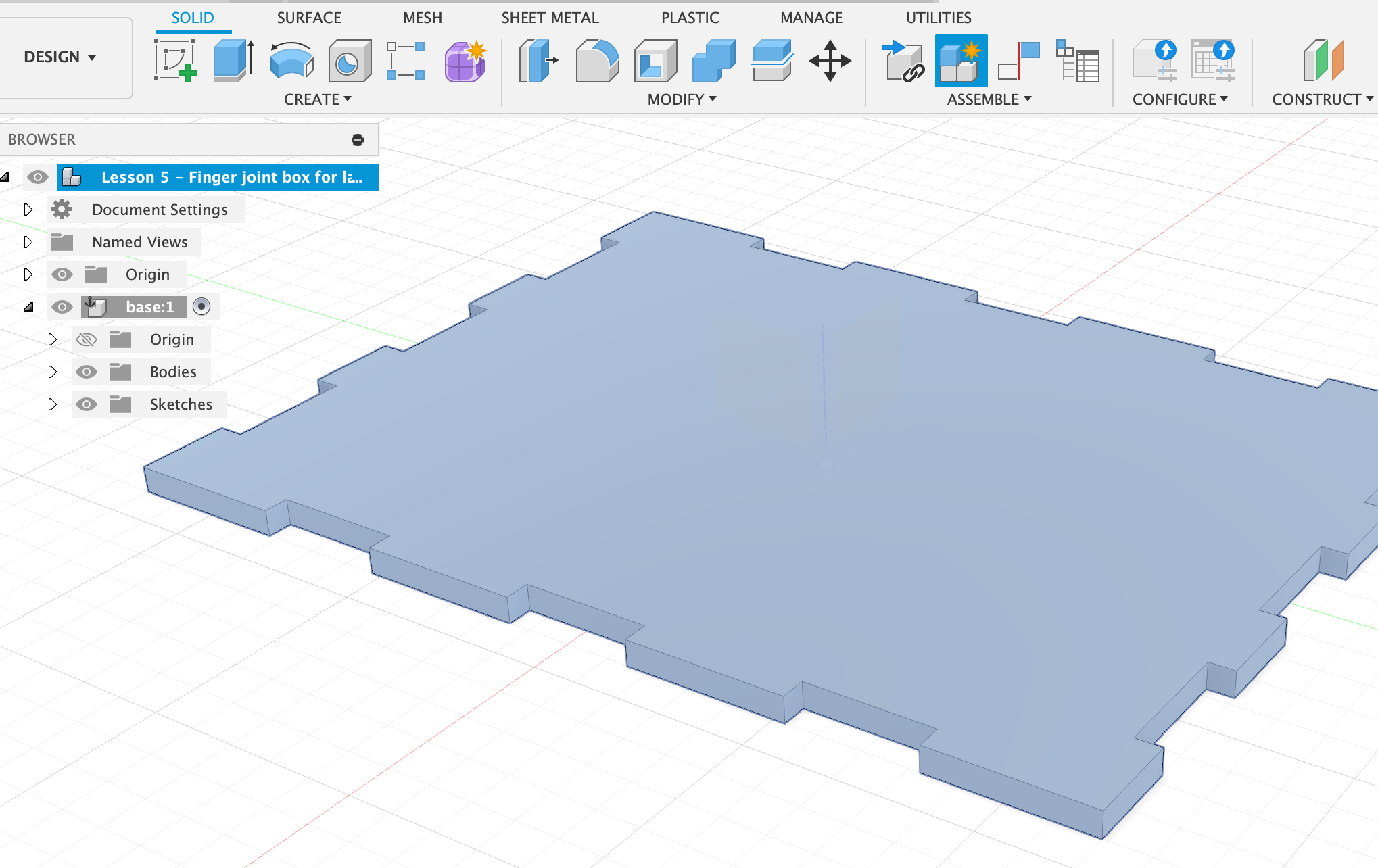
Activate the top level component and create New Component. Name it “long side”. Create a sketch at the edge of the long side of base. Press “p” to project and select all the surface along the long edge. Then draw a rectangle over the whole thing. The height of the rectangle should be “height”.