Lesson 1 - Designing a simple toolbox Lesson 2 - Creating plans for your model Lesson 3 - Making smart models Lesson 4 - Revolving, cutting holes, removing material Lesson 5 - Finger joint box for laser cutting Lesson 6 - Laptop stand with box joints Lesson 7 - Open top finger-jointed box Lesson 8 - Making holes Lesson 9 - Preparing files for laser cutting
Beginner tips
Rule #1 for beginners
https://www.youtube.com/watch?v=ZYXSJ6EQ9S4
- Always name and save your project before you start.
- Create a component first. New > Create component. Name the component, e.g. “box”. Create your sketch and extrude it. Then in the browser select the top level again, and create another component. Name it, e.g. “lid”. Sketch, extrude.
- This way your design history is very short and concise for every component. It’s also much easier possible to isolate a component and only work on that component. Keeps everything more organised.
Beginner’s guide
https://youtu.be/7lKpzGtoQX0?si=p9I_6OVjWW_BalAi
Baseplate
- Create a new project. Name it.
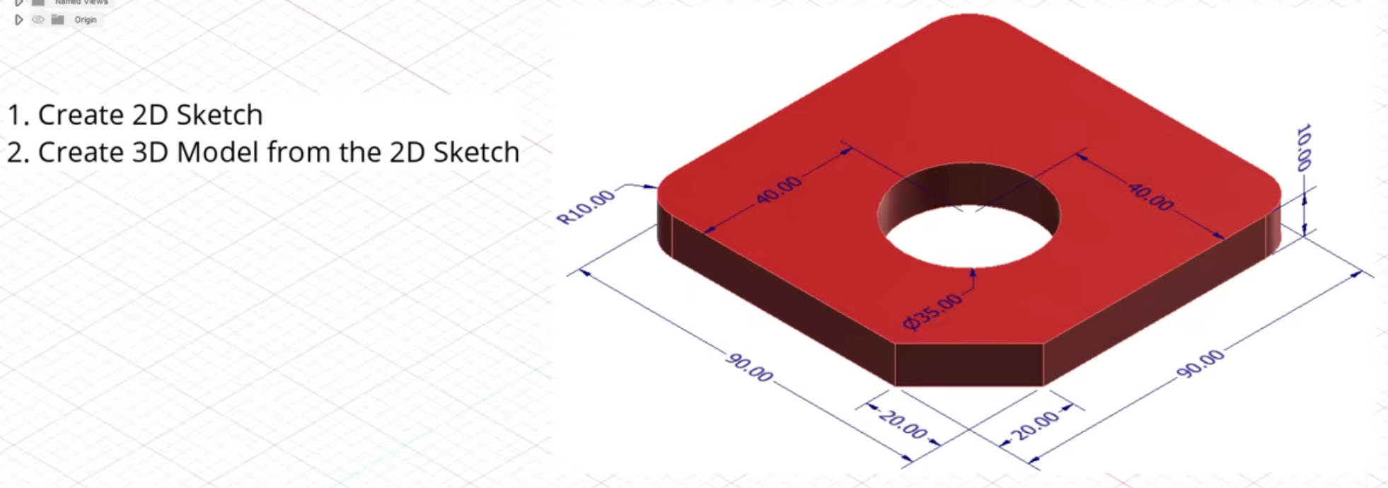
- Create sketch. Bottom plane. 2-point rectangle. Start it at origin, draw it out, then type in 90 mm for the length - TAB - 90 mm for the width - ENTER.
- To make the chamfer: Sketch a line from one side across the corner to the other side. Don’t care about dimensions. Then select Dimension (shortcut d): select the endpoint of the drawn line and the origin, enter 20 mm, ENTER. Do the same for the other endpoint of the line. This will adjust the position of the diagonal line.
- If a line is blue in colour, it means it’s not fully constrained. If it’s black, it’s fully constrained and can’t move any more.
- To make a hole in the middle: Circle tool, place a circle anywhere in the square. Diameter 35 mm. Dimension: Click on the outline of the circle, then to the left side of the square, 40 mm, ENTER. Dimension: Click on the outline of the circle, then on the bottom side of the square: 40 mm, ENTER. Circle is now fully constrained, i.e. black.
- For fillets: Modify tools: select Fillet. Click on the left side of the square and the top side of the square. The outline of a fillet appears. Enter the size of the filler, 10 mm. ENTER.
- Finish sketch.
- To make 3D model: Solid > Extrude. Select the correct profile, which is the main square bit, i.e. not the circle and not the chamfer. Distance: 10 mm. New body.
- Click on the small house next to the view cube to get to Home view.
- Modify > Appearance to change the skin of the part. Drag the selected colour or finish onto the surface or body you want to change.
Bracket

- Start with the footprint. Sketch on the bottom (XY) plane. 2-point rectangle, 80x80 mm. Make a chamfer as before with the Line tool and the Dimensions tool, as above in the base plate. Make a Circle with diameter 30 mm, and position it 40 from left edge and 40 from bottom edge with the Dimensions tool. Finish Sketch. Solid > Extrude, select the base plate and extrude up 10 mm, as New Body.
- For the back plate (wall), select Sketch, and then the upper face of the base plate as the sketching plane. Draw a Rectangle on one long side of the base plate (inside the base plate). Dimension the wall thickness as 10 mm. Make another rectangle on the other long side, so that it overlaps in the corner with the first rectangle. Also wall thickness 10 mm.
- Finish sketch. Extrude, select all three parts of what should be the wall. Thickness = 40 mm, select Join to join the walls together, as well as to the base plate.
- To insert the fillet in 3D mode: Modify > Fillet, select the inner corner of the walls. Type in 5 mm, leave everything else as is (rolling ball, constant radius). Add another fillet to the outer corner of the walls with 15 mm radius.
- Create a hole on each wall side by creating a Sketch on its face. 15 mm diameter, distance from bottom 20 mm, distance from side 35 mm. Extrude to -10 mm, operation: Cut.