https://www.youtube.com/watch?v=9U2JPfkQpsE The tabs of the joints should automatically adjust themselves when changing the dimensions of the box.
Define parameters
- length, mm, 150
- width, mm, 75
- height, mm, 30
- thickness, mm, 3.175
- lengthFingers, no unit, 5
- widthFingers, no unit, 3
- heightFingers, no unit, 2
- Formulas that will base the width of the fingers on the dimensions
- lengthFingerW, mm, length/((lengthFingers x2)+1) (=13.636)
- widthFingerW, mm, width/((widthFingers x2)+1)
- heightFingerW, mm, height/((heightFingers x2)+1)
Bottom plate
- Create sketch.
- Select x-y plane (bottom plane).
- Draw a 2-point rectangle with defined width and length.
- Extrude with defined thickness.
- Rename the body in the browser tree to “Bottom panel” and the sketch “Bottom panel sketch”.
- Now create the fingers along the length of the bottom panel.
- Create sketch, select the front-facing face of the bottom panel as the plane.
- Draw a 2-point rectangle across the front. Make sure you start at a point directly on the bottom line (green X will appear) and draw the rectangle until it’s exactly at the upper line (green X will appear = constrained). Don’t type any measurements or units into the inputs, this will break the constraints!!! Just click on the edge. When two black dots appear it means that the corners are constrained to those edges.
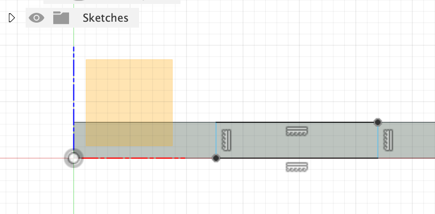
- With “d” make the length of the little rectangle lengthFingerW.
- Also make the distance from the left corner lengthFingerW, so that the finger and the notches are the same length.
- Finish sketch
- Extrude the one finger to -thickness to cut it into the bottom plate. This combination of lines and operations is called a feature.
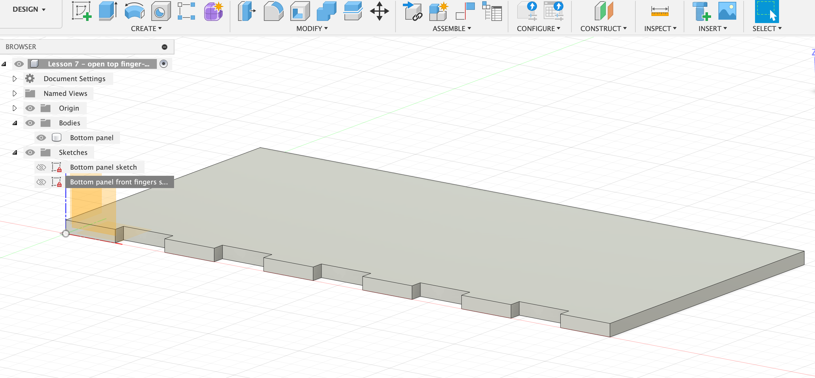
- Create > Pattern > Rectangular Pattern (NOT the one from the Sketch menu!).
- Select feature and click on the extruded feature we just created.
- Select for axis the long axis towards the right corner (arrow should point to the right).
- Quantity: lenghtFingers
- Distance: length - lengthFingerW x3 (should the arrow for direction point into the left direction, then you’d have to type a minus before this expression).
- OK
- Rename the current sketch in the browser “Bottom panel front fingers sketch”.
- Test that changing the parameters (e.g. lengthFingers = 10) actually adjusts the object correctly.
Front panel
- Create sketch on the x-z (front) plane.
- Make a 3-point rectangle with left corner at origin, right lower corner at the end of the bottom panel, and upwards dimension height. Finish sketch.
- Extrude towards the inside of the box with thickness. Operation = New body. OK
- Rename the body in the browser to “Front panel” and the sketch to “Front panel sketch”.
- Right-click on the surface of front panel, choose Appearance and tick Faces in the appearance menu. Drag a different surface onto it, e.g. Cherry. Do so with the other 3 flat sides of the two existing panels. Now we can see that something weird is going on with the fingers of the joint. They seem to be both cherry wood and not. This means there is some interference.
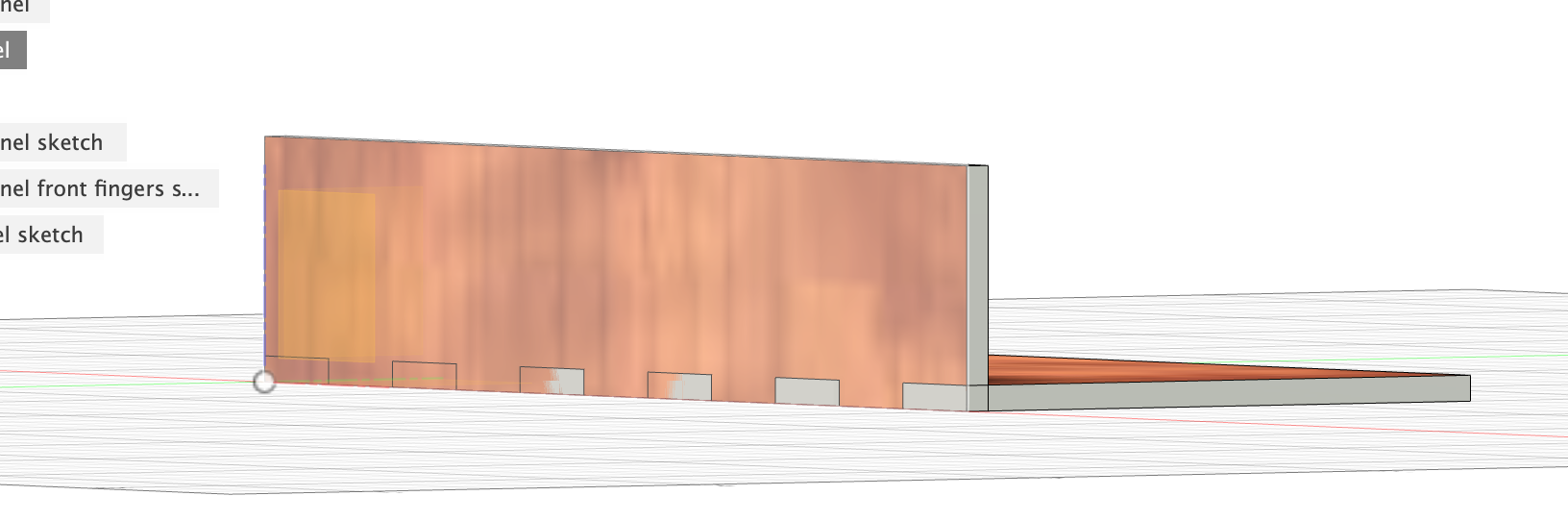
- To fix the interference, select Modify > Combine with front panel as Target body and bottom panel as Tool body. Operation = cut. Check Keep Tools. Interference is gone now and the fingers are cut into the front panel.
- Now create fingers on the left side of the front panel.
- Create sketch with plane being the left face of the front panel.
- Draw a 2-point rectangle on it that is constrained to both edges. Dimension its length as heightFingerW. Dimension the distance from rectangle to very bottom edge of the panel as heightFingerW. Finish sketch.
- Extrude a cut into the panel with -thickness.
- Rectangular Pattern from that finger cut feater, extending upwards, Quantity = heightFingers, Distance = height-heightFingerW x3.
- Rename that sketch to “Front panel left fingers sketch”.
Back panel
- “Copy” over the front panel by extruding:
- Extrude, select the front panel.
- Select Start = From Object and click the back face of the bottom panel.
- Depending on if the arrow points towards or away from the front panel, type thickness or -thickness.
- Select New Body. OK.
- Now construct the notches in the bottom panel as above.
- Combine. Target = bottom panel, Tool = back panel. Cut. Keep tool.
Left panel
- On the left face of the bottom panel create fingers:
- Create sketch.
- Draw rectangle constrained to both edges. Width = widthFingerW. Dimension the distance to edge with same parameter. Finish sketch.
- Extrude with thickness into the plate. Cut.
- Rectangular Pattern, select feature, select direction. Quantity = widthFingers, Distance = width - widthFingerW x3.
- Create sketch on y-z-plane. 3-point rectangle: corner, corner (origin), top front corner. Finish sketch.
- Extrude thickness. New body.
- Appearance, change the faces to cherry wood. Interferences visible.
- Combine: Target = left panel, Tool = back, bottom, front panels. Cut. Keep tools.
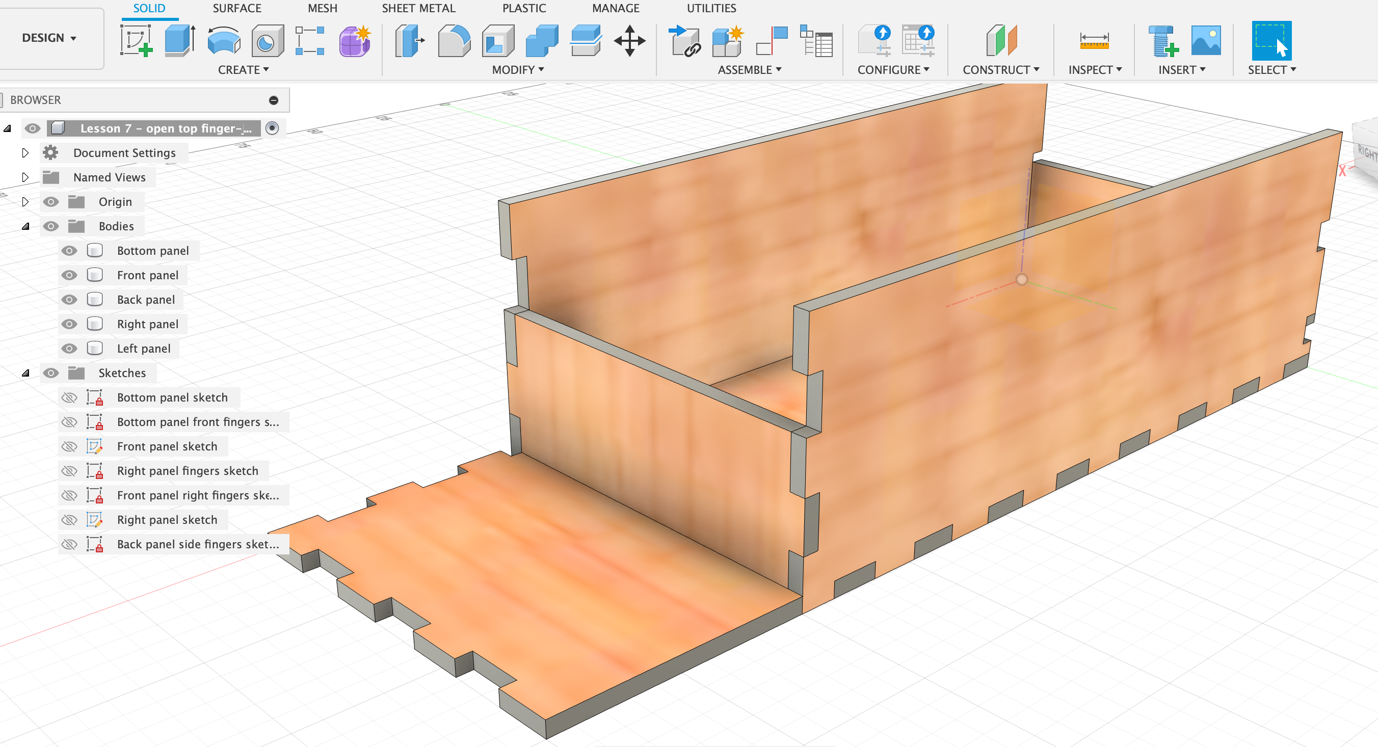
Right panel
- Extrude the left panel, start = from Object, click right face of bottom panel, thickness, New Body.
- Change Appearance of the faces.
- Combine: Target = right panel, Tool = back, bottom, front panels. Cut. Keep tools.
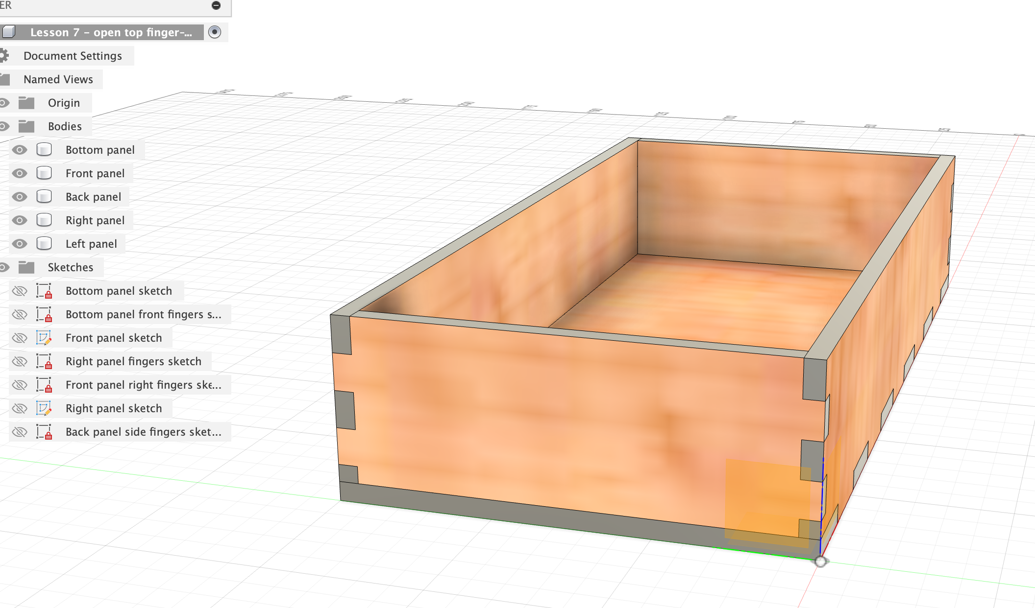
Try to change some of the parameters to check if everything works fine.
Something did not work…