
2025-07-26
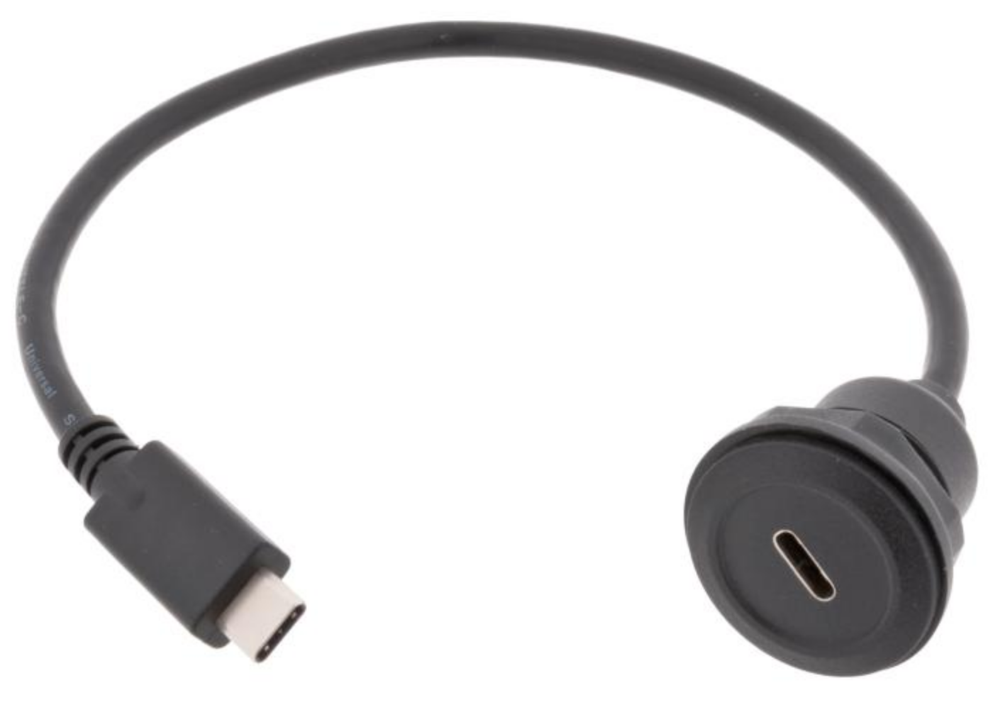
Order USB-C flange connection https://www.electrokit.com/adapterkabel-usb-c-till-usb-c-panelmonterad that can be mounted on one side of the box for the power connection.
2025-08-05
Fusion 360
Download Autodesk Fusion360 for personal use https://www.autodesk.com/products/fusion-360/appstream
Questions
Things to test on the Fusion360 prototype:
- How big to make it (rather as the smaller cardboard prototype?)
- How to arrange the switches: 4x2 or in random configuration?
- Where to put the USB-C power slot and the speakers
- How to make the speaker grills ⇒ find some inspo pics
- Should we make the box “reversable”, i.e. you can stand it upright?
- How to attach the volume knob to the box (doesn’t currently have a flange)
- Which side to open and how?
- Back openable. Pros: can use box joints for most sides; no need for hinges. Cons: back panel access is very limited, especially on the small size model.
- Top as a flippy lid with hinges. Pros: more and easier access to insides. Cons: Can’t use box joint for all the sides touching the top plate; not as sturdy as box joints; maybe a bit wobbly when working position of the box is flipped from horizontal to vertical. Other considerations: top panel needs to be sanded down to a <90o angle.
- Should we add a volume knob? Where should we place it? On the side or on the top? And if on top, how to arrange it together with the switches?
Tutorials
Watch and follow along this tutorial https://www.youtube.com/watch?v=Izh99EnGLGw
2025-08-21
Designing the prototype in Fusion 360
Rough dimensions (need to be adjusted to fit):
bottom plate: 16x23 cm back plate: 10x 23 cm front plate: 3.5x23 cm top plate: 16x23 cm material thickness: assum 3 mm for now
Inspo for speaker grills: https://www.speaker-grill.com/?ref=blog.duncangeere.com
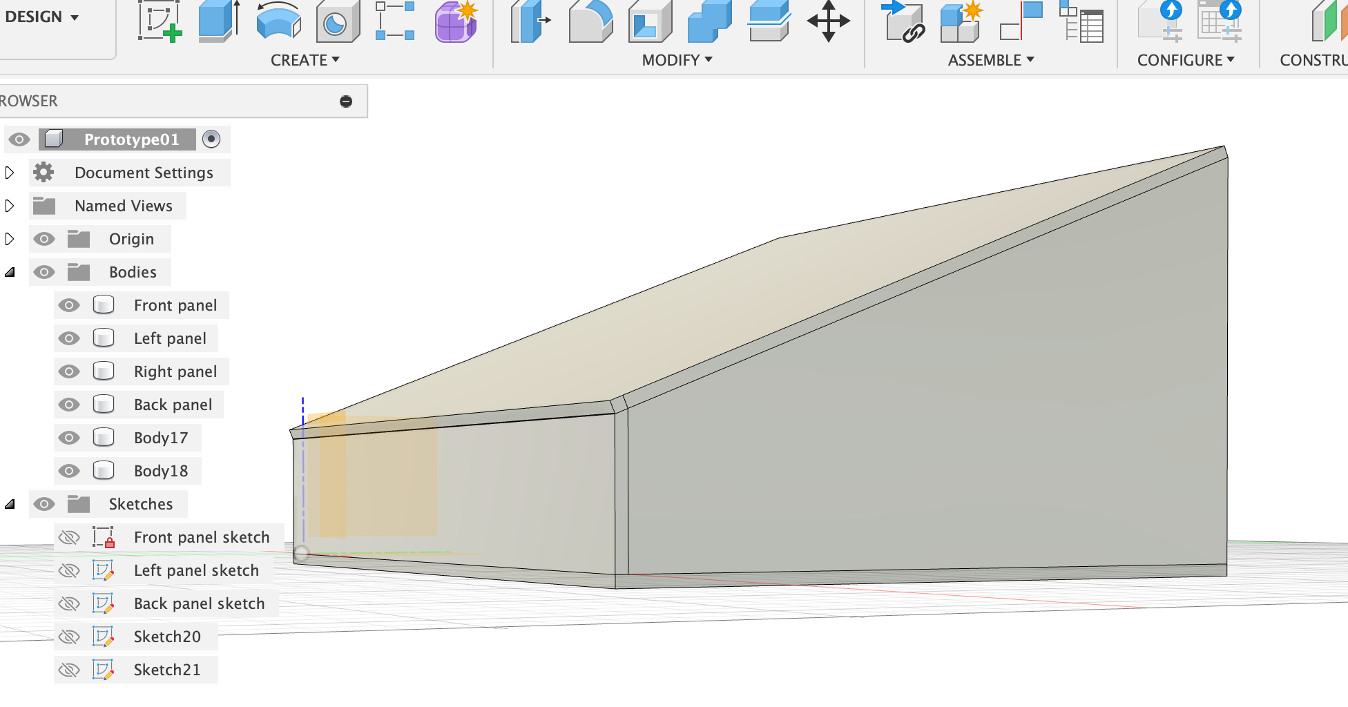
3D protoype 1
Try without box joints for now.
Start with sketching the side profiles with lines.
RIGHT
For this profile, don’t use parameters yet, but once the dimensions work, set parameters for most of them.
BACK
Actually, the length of the back panel needs to be bottomPanelLength+2x thickness instead of just bottomPanelLength.
FRONT
LEFT
Extrude the right side “from object” and select the left face of the front plate to extrude from. Thickness = thickness.
Gets too complicated (for now) with little non-90-degree angles at the intersections of the four sides… Make it easier for now. Use 90 degrees everywhere!
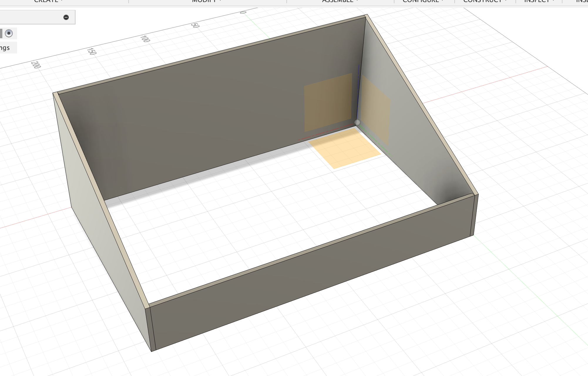
Protoype 02
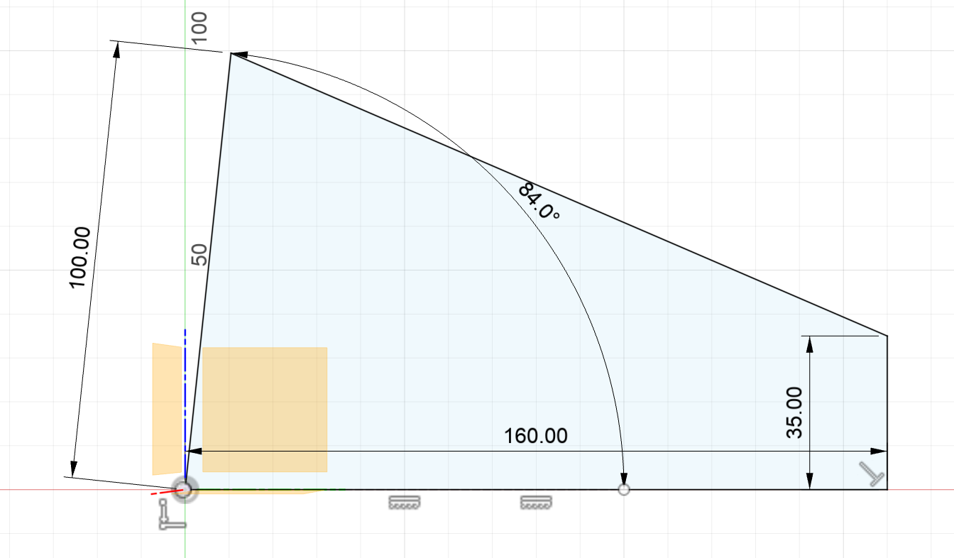
Parameters: bottomPanelLength = 230 mm bottomPanelWidth = 160 mm thickness = 3 mm backPlateWidth = 100 mm frontPlateWidth = 35 mm
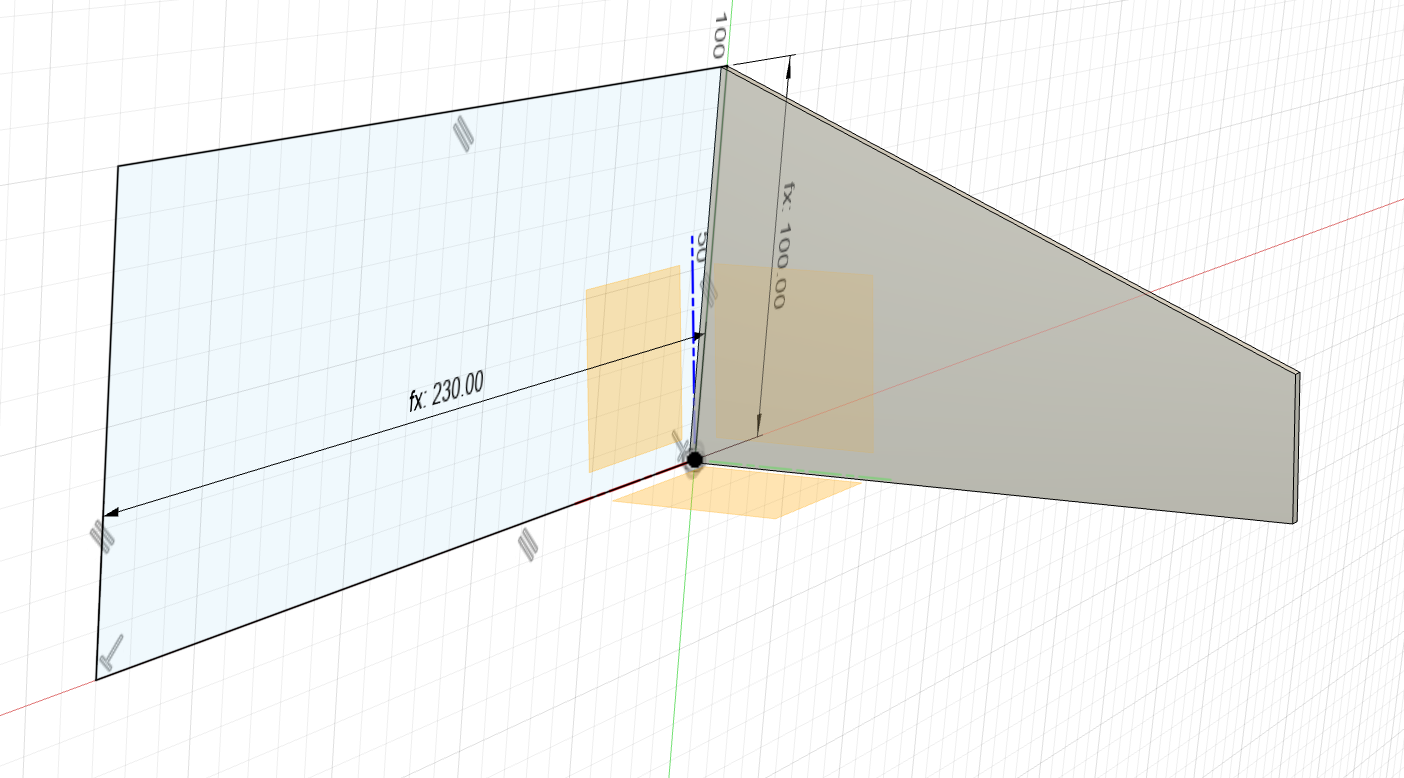
FRONT Make first. l = bottomPanelLength + 2xthickness h = frontPlateWidth Extrude outwards.
LEFT Sketch, then extrude inwards. l = bottomPanelWidth h = backPanelWidth Extrude inwards.
The edge of the front plate has to be filed down manually later so the top plate closes nicely.
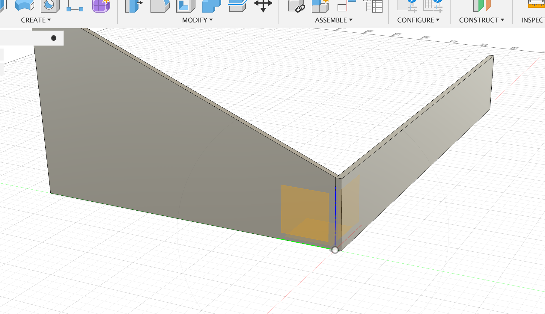
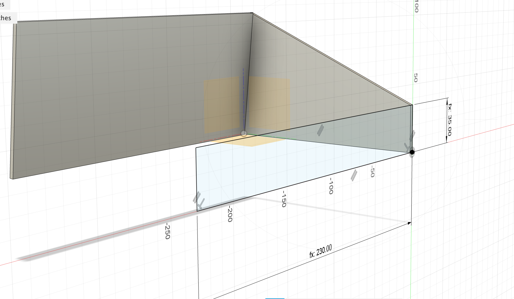
RIGHT
Extrude the left panel with offset bottomPlateLength and thickness thickness towards the right side.
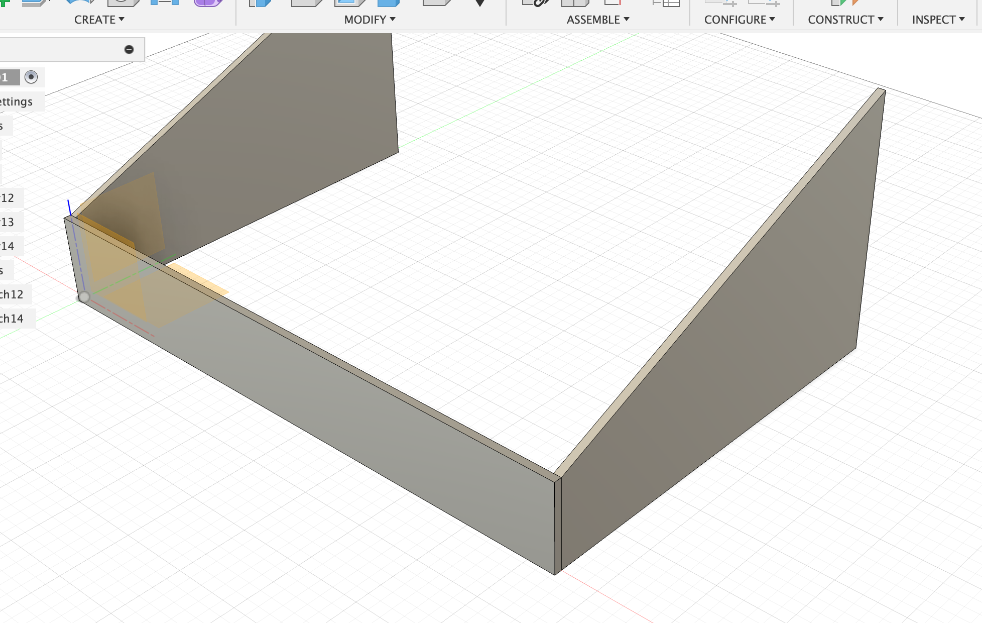
BACK
Make the sketch so that it’s on the inside corners of the extruded side panels, and then extrude the back panel with thickness thickness towards the inside.
This way, the top of the back panel can be filed down a bit to match the angle.
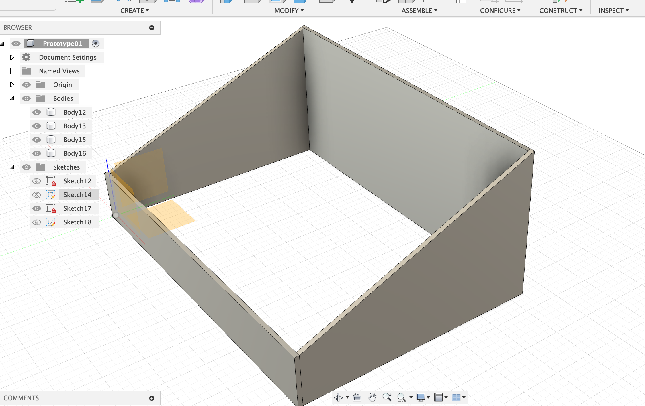
TOP & BOTTOM
Make top and bottom plates flush with the outermost corners, extrude thickness. Edges that are sticking out can be adjusted later manually by filing.
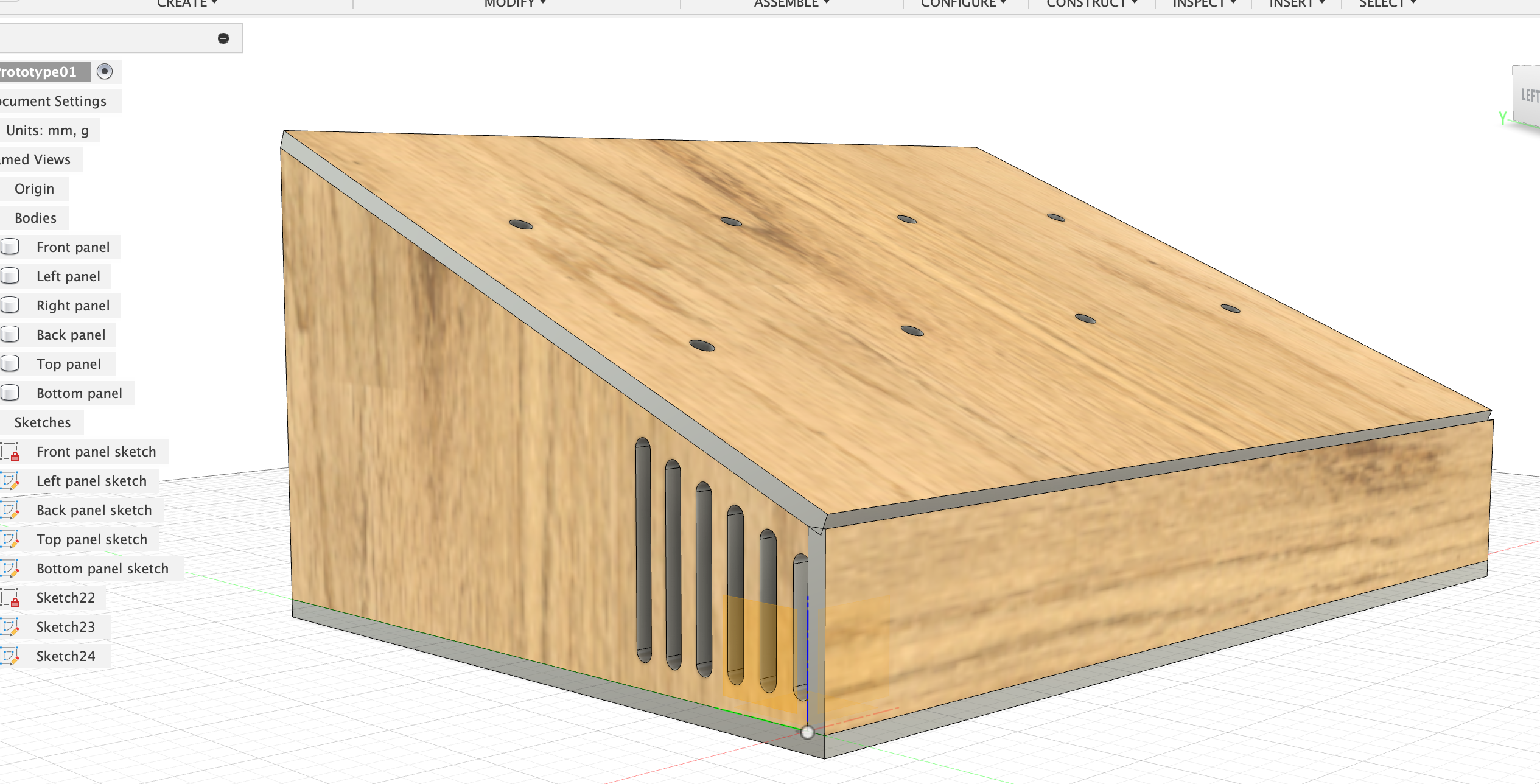
Ok, general outline of the box is done!
Insert slots with slot tool and holes with holes tool:
2025-08-24
3D Prototype 2
For uploading on the laser cut website, they need .dxf files. In the free version of Fusion 360 it seems like that can only be done from sketches. The problem with Prototype 1 is that some of the elements, like the slots, are not an integral part of the sketch of the side panel, but their own sketch. In addition, the laser cut service only has 4 mm strong plywood. When I change my thickness parameter in Prototype 1 it mostly works, but not perfectly. There are some weird things happening that I’d need to fix. Like the slots sliding too close to the edge because I tied their dimensions to thickness in a slightly suboptimal way. When testing the upload to the laser cut service I also saw that some of the sketches have some errors like “Linjer eller former överlappar varandra”. So! The strategy for now is:
- Dimension the box with 4 mm plywood.
- Get the placements of the slots and holes perfect (measure the components like speakers).
- When sketching holes and slots, make sure they happen on the original sketch for that panel.
- Occasionally save a sketch and upload it to https://order.scandcut.se/quote/ to see if there are still errors with the sketch.
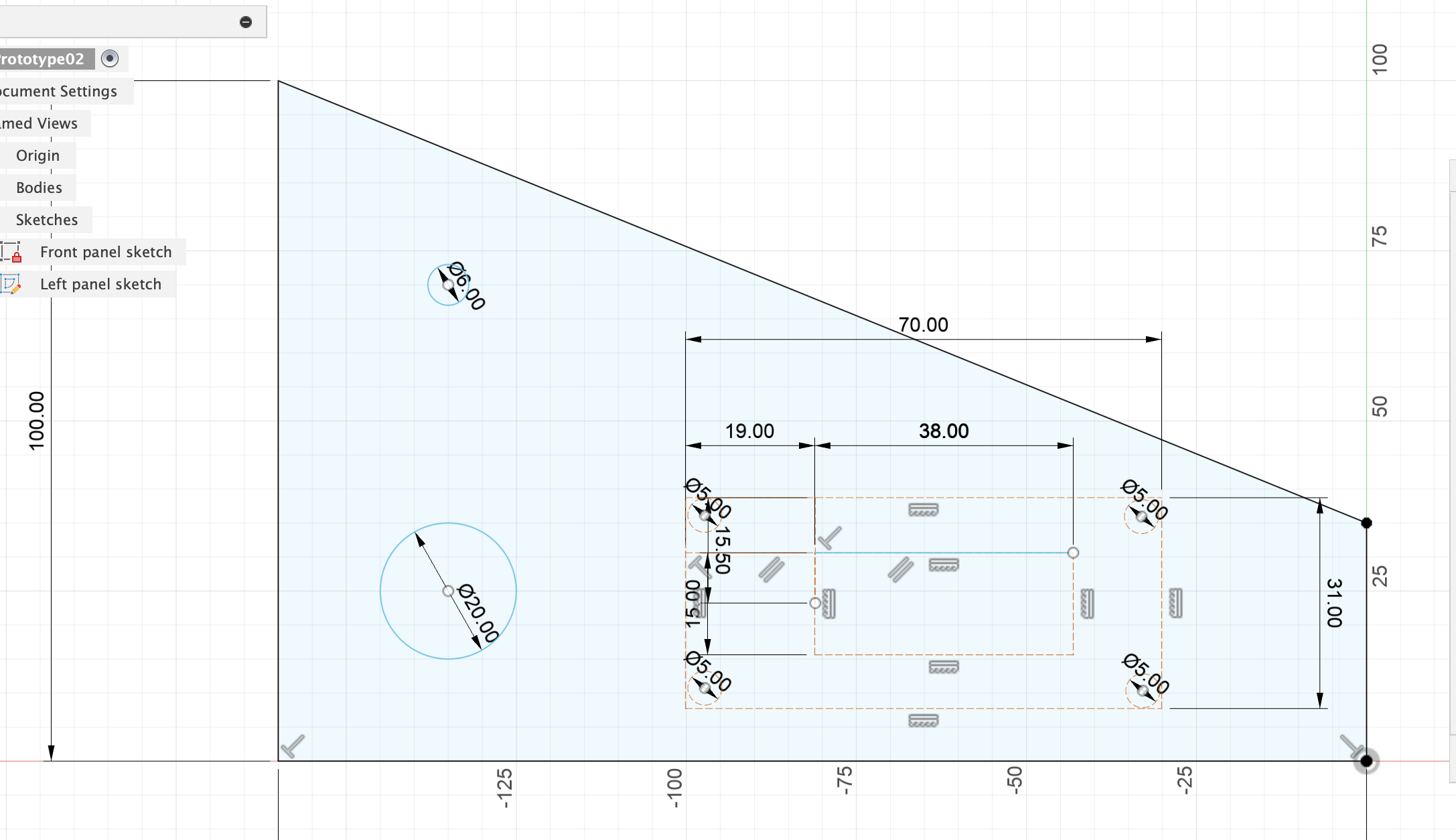
Important dimensions:
-
Speakers:
- l = 70 mm
- w = 31 mm
- middle part: 19 mm - 38 mm - 13 mm
- screw-holes on the edges: 1 mm and 2 mm from the edges, 3 mm in diameter
-
USB-C connection: 20 mm in diameter
-
Switches and knobs: 6 mm in diameter
Parameters: thickness = 4 mm length = 230 mm width = 160 mm frontHeight = 35 mm backHeight = 100 mm
FRONT The front panel should cover the sides of the side panels. The side panels should “tuck in behind” the front panel so that the slope of the side panels can be nicely match the front panel (with some sanding down) and the top panel can sit flush on all sides.
Make first.
l = length (230 mm) h = frontHeight (160 mm) Extrude with thickness (4 mm).
LEFT
Sketch onto left facing of front panel. Sketch the outer perimeter with line tool:
- front height = frontHeight (35 mm)
- back height = backHeight (100 mm)
- bottom width = width (160 mm)
- top width = just connect the dots.
Then sketch the position of the USB-C hole (20 mm diameter) and on/off knob hole (6 mm diameter). Double check with knob specifications that that is actually true!!!
Sketch with construction lines the position of the speaker and the position of the screw holes of the speaker. Determine where the slots can go.
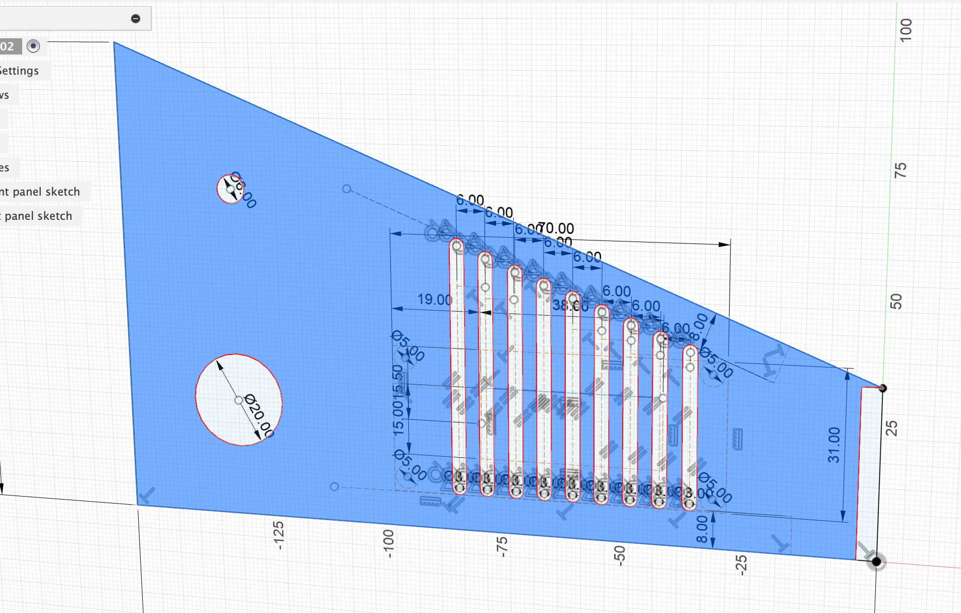
Sketch the speaker holes/slots:
- Make construction lines 8 mm away from the bottom and top edges - 8 mm so it’s a good bit away from the bottom edge and the top edge.
- Make the slots 3 mm in width. Somewhere it was suggested to not make slots thinner than material thickness, but 3 mm is already quite large (don’t think it will be a problem for the laser), and 4 mm seems a bit too wide.
- Distance between slots also 3 mm, so from mid point of slot to mid point of slot 1.5 + 3 + 1.5 = 6 mm.
Make sure that all lines that are not used for extruding are marked as construction lines. Double-check by clicking on the main part of the sketch and see what is coloured blue:
For some reason the right-most part that sits on the facing of the front panel is not included in the sketch. Delete the line (sketchline) and try to delete the two points. I can only delete the top sketchpoint, but not the bottom one.
Save as a separate file, then delete all unnecessary (construction) lines and labels. Then export as DXF file with visible geometry, points and projected geometry all unticked.
⇒ No errors when uploading the file to scancut.se