https://youtu.be/7riGolu7BpA?si=DbyL7aPWSvvxJhE1
Make leg components
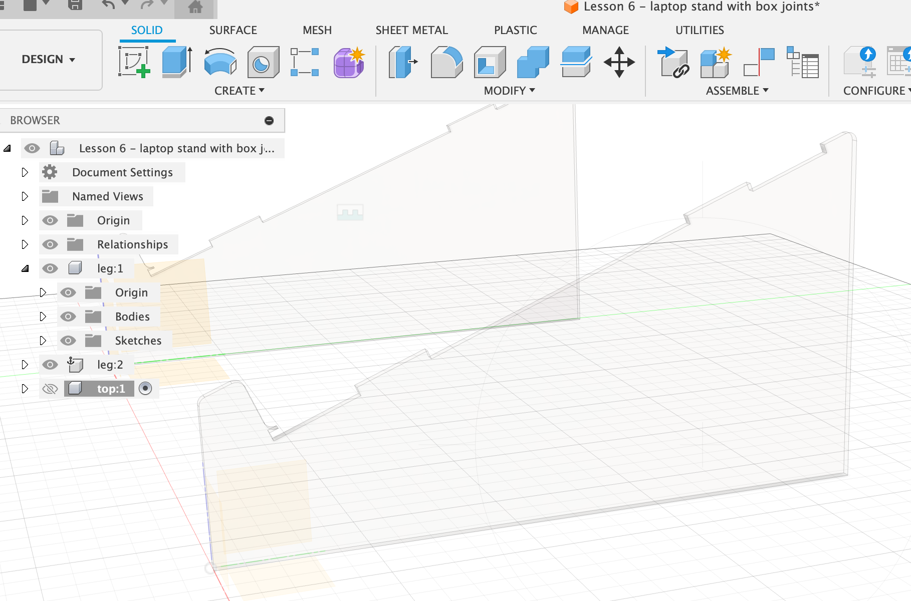
- Righ-click top of the browser (to the left), pick New component. Name it leg.
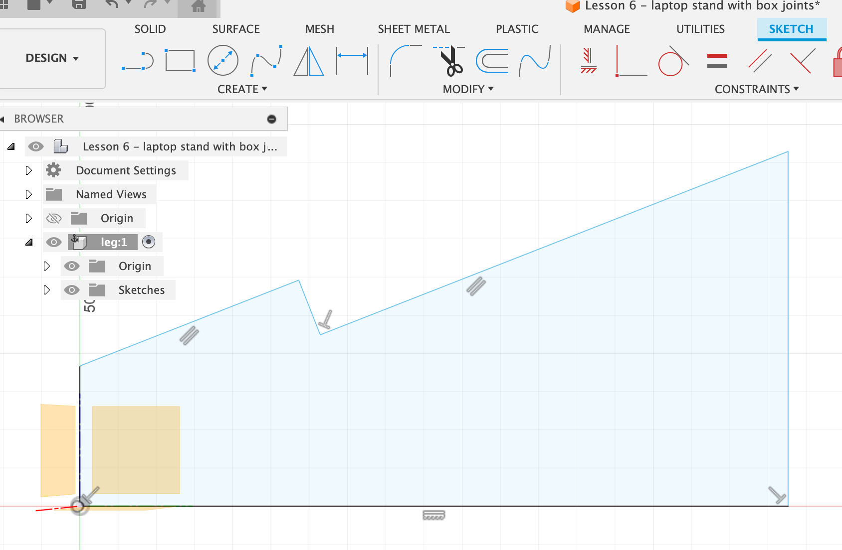
- Start to make a sketch at the back vertical plane.
- Turn on the origin under the leg component in the browser to keep everything aligned.
- Sketch out the rough outline of the laptop stand. Use some constraints where applicable, e.g. a right-angle constraint where the laptop rests. In the sketch, the constraints are visible with little symbols. E.g. wherever there is a right-angle constraint (perpendicular) there’s a little T symbol on the sketch.
- Make the two slanted lines constrain to be parallel. Shift-click both of them, then select Parallel.
- Dimensions: Pick the Sketch Dimension tool (or press d). Bottom should be 225 mm, right height 125 mm, left height 55 mm, leaning angle of laptop 22 degrees (for that, select the two lines that make up the angle, i.e. the slanted one and the bottom one), upper piece of ledge 14 mm.
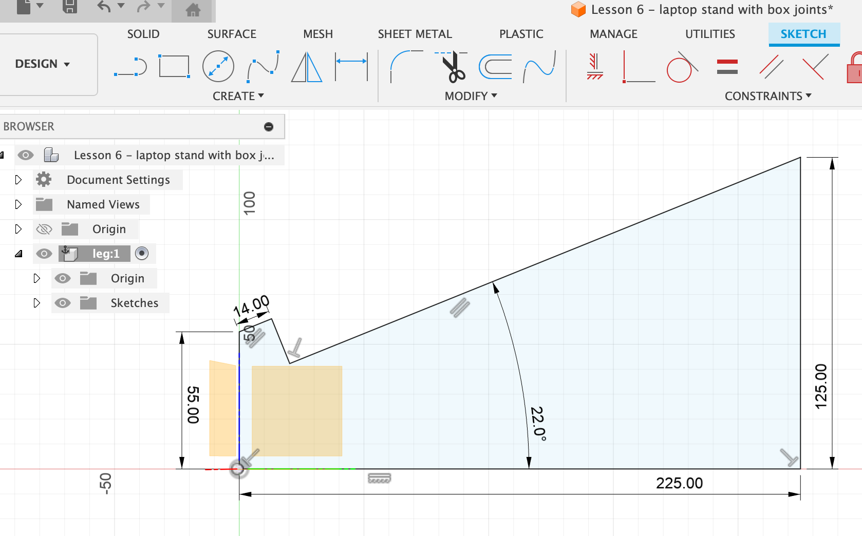
- Finish sketch.
- Define a user parameter (Modify > Change parameters) for thickness of material: thickness, mm, 3. Define one for legWidth (how far apart the legs should be, depends on laptop): legWidth, mm, 270.
- Extrude the profile with thickness “thickness”.
- Round off edges using Modify > Fillet. Click on the little lines at the edges to round off the corners, 3 mm.
- To make a duplicate of this leg:
- Right-click on the top level item in the left-hand browser and select Activate.
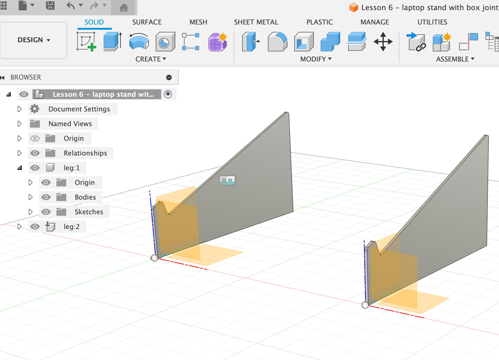
- Right-click on the leg component in the browser, and select Copy. Actual copy (i.e. command+c), not Move/Copy.
- Paste (command+v) it into the workspace and don’t move it yet (it will be just on top of the other). Any changes on one of them will be applied to the other. In the browser a new component called leg 2 has appeared.
- Define the distance between the two legs. Use the Assemble > Joint option for that. Joint positions components relative to each other in an assembly.
- Choose Joint.
- Click the first point onto the outside face of the visible object. There’s a little square icon that appears on the surface where the cursor snaps to. Choose this point.
- Rotat the object around to see the other face.
- Click the second point on the outside of the face, snapping right onto the point of the other side.
- In the context dialog box, put in legWidth for Offset z axis. OK.
- Test under Modify > Change parameters if the design adapts when you change the legWidth and thickness parameters.
Make the top shelf
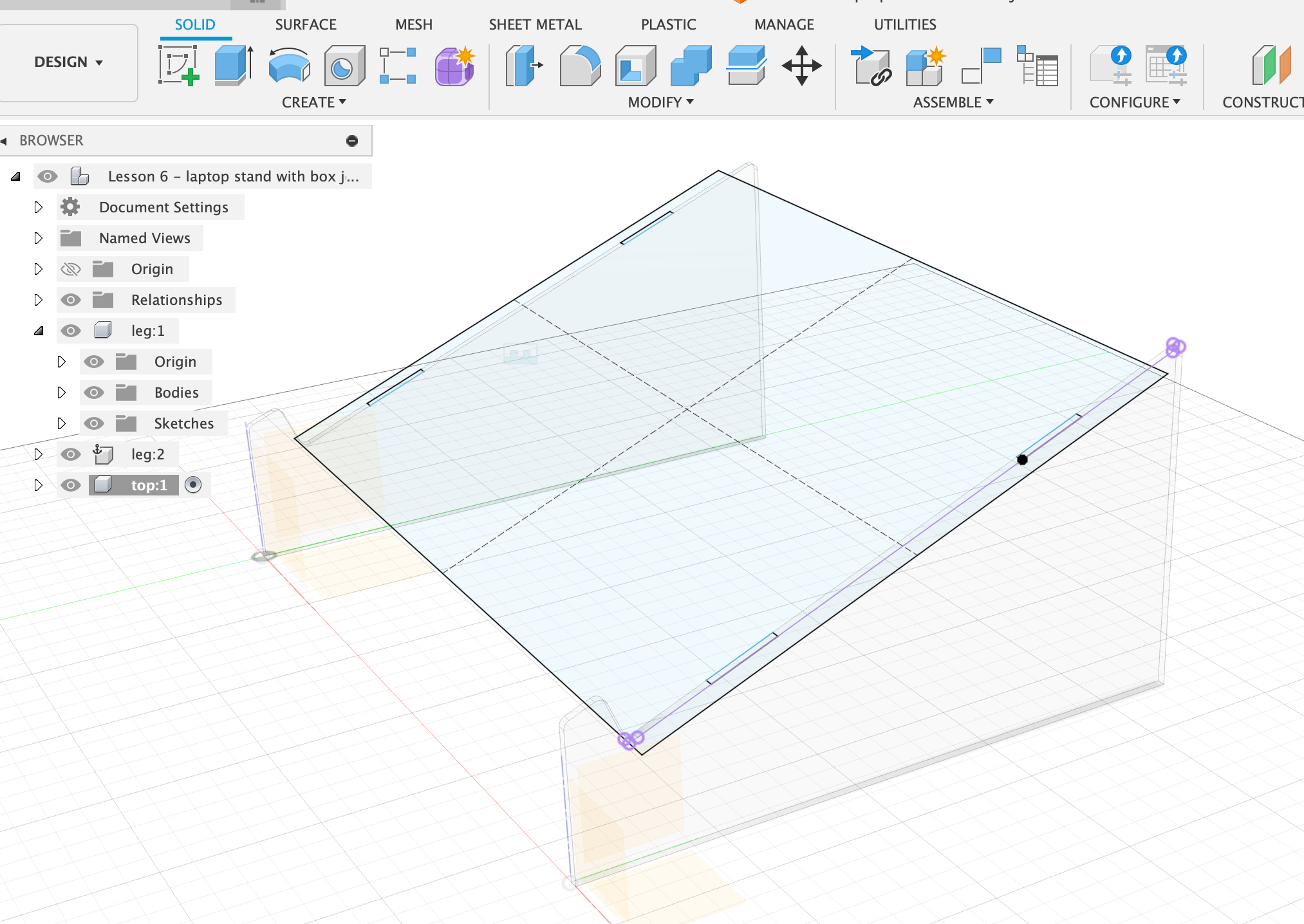
- Right-click on the top-level browser item, choose New Component. Call it top.
- Create a new sketch off of the existing surface of the legs, the surface where the top plate should rest on. Just click that edge of the leg to set it as the sketching plane.
- To also project in the other geometry, make sure that Project geometry is checked in the Sketch dialog box.
- To get a good view on a specific component, click the Look at icon on the bottom of the window, then select the surface of the slanted edge of one of the leg components.
- Draw a rough 2-point rectangle over the slanted leg part.
- Choose the lower edge of the rectangle and the little line where the slanted part of the leg ends (i.e. where you want the plate to rest and end), then choose Constraint > Colinear. This will make the two lines share a common line, i.e. the top board will end exactly where the slanted part of the leg ends.
- For the top edge of the rectangle, just drag it a bit down so it doesn’t stick out over the legs.
- With Sketch Dimensions set the distance between top edge of top plate to the top edge of the legs to 12 mm.
- Set the distance of the top plate sticking out left and right to 8 mm.
Make the box joints connecting top plate and legs
- Draw two rectangles onto the top plate that align perfectly with the top surface of the legs.
- Set the length dimension of the rectangle to 25 mm, and the distance from rectangle to top of top plate 30 mm.
- Draw mirror lines to mirror the tabs:
- Choose line tool.
- Draw a line on the top plate from top to bottom, in the centre, and from left to right, in the centre.
- Set the mirror lines to construction lines with x (or in the right-hand menu).
- Click Mirror, then select the 4 lines of the little rectangle. Mirror across the top plate.
- Click Mirror again, then select the 8 lines of the two little rectangles. Mirror from top to bottom of top plate. Finish sketch.
Extrude the top plate
- Select all pieces that should be extruded, i.e. the top plate but NOT the little tabs.
- Extrude downwards by selecting the thickness as -thickness.
- Now we need to make sure the tabs from the legs and the top plate don’t interfere with each other ⇒ Perform Boolean operation to subtract one from the other.
- Modify > Combine
- Target body = the one that the actions are being performed on. We want to remove material from the legs, so choose leg as target body.
- Tool body = top plate.
- Operation = cut.
- “Keep tools” need to be checked in order to keep the top plate. > OK.
- Hide the top plate to see if the tabs have been correctly cut out of the legs. This operation only needs to be done on one leg, since the other is a copy.
Little adjustments
- Fillet the edges that shouldn’t be so pointy.
- Check if everything works by changing the thickness and width parameters.
- To change between orthographic (straight on) view and a more perspective view, right-click on the little cube in the top right corner.
- To centre the view on a specific surface, click on the bottom icon Look at, then select a surface.
PROBLEM: When adjusting the legWidth, the tab cutouts on the top plate don’t move accordingly!